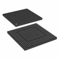
MPC8308VMAGD Freescale Semiconductor, MPC8308VMAGD Datasheet - Page 891

MPC8308VMAGD
Manufacturer Part Number
MPC8308VMAGD
Description
MPU POWERQUICC II PRO 473MAPBGA
Manufacturer
Freescale Semiconductor
Datasheets
1.MPC8308VMAGD.pdf
(90 pages)
2.MPC8308VMAGD.pdf
(2 pages)
3.MPC8308VMAGD.pdf
(1170 pages)
4.MPC8308VMAGD.pdf
(14 pages)
Specifications of MPC8308VMAGD
Processor Type
MPC83xx PowerQUICC II Pro 32-Bit
Speed
400MHz
Voltage
1V
Mounting Type
Surface Mount
Package / Case
473-MAPBGA
Product
Network Processor
Data Rate
256 bps
Frequency
400 MHz
Supply Voltage (max)
3.6 V
Supply Voltage (min)
3 V
Supply Current (max)
5 uA
Maximum Operating Temperature
+ 105 C
Minimum Operating Temperature
0 C
Interface
I2C, JTAG, SPI
Mounting Style
SMD/SMT
Lead Free Status / RoHS Status
Lead free / RoHS Compliant
Features
-
Lead Free Status / Rohs Status
Lead free / RoHS Compliant
Available stocks
Company
Part Number
Manufacturer
Quantity
Price
Company:
Part Number:
MPC8308VMAGD
Manufacturer:
FREESCAL
Quantity:
300
Company:
Part Number:
MPC8308VMAGD
Manufacturer:
Freescale Semiconductor
Quantity:
10 000
Part Number:
MPC8308VMAGD
Manufacturer:
FREESCALE
Quantity:
20 000
Company:
Part Number:
MPC8308VMAGD400/266
Manufacturer:
FREESCAL
Quantity:
300
Company:
Part Number:
MPC8308VMAGDA
Manufacturer:
Freescale Semiconductor
Quantity:
10 000
- MPC8308VMAGD PDF datasheet
- MPC8308VMAGD PDF datasheet #2
- MPC8308VMAGD PDF datasheet #3
- MPC8308VMAGD PDF datasheet #4
- Current page: 891 of 1170
- Download datasheet (9Mb)
16.4.1
Table 16-2
standard, 2000 edition. Input signals not used are internally disabled. Except for TSECn_GTX_CLK,
output signals not used are driven low.
Freescale Semiconductor
TSEC_TMR_ALARM1 1588—Alarm out 1
TSEC_TMR_ALARM2 1588—Alarm out 2
TSEC_TMR_TRIG2
TSEC n _TMR_RX_
TSEC n _TMR_TX_
TSEC_TMR_PP1
TSEC_TMR_PP2
TSEC_TMR_PP3
TSEC n _CRS
TSEC n _COL
Signal Name
Signal
ESFD
ESFD
is a description of the eTSEC interface signals. All other modes follow the IEEE 802.3
Detailed Signal Descriptions
For more information on RGMII mode, see Hewlett-Packard Reduced
Gigabit Media-Independent Interface (RGMII) Specification, Version 1.2a,
Dated 9/22/2000.
Table 16-1. eTSEC n Network Interface Signal Properties (continued)
I/O
1588—Trigger in 2
External timer trigger input 2. This is an asynchronous general purpose input (chip external
input pin).
1588—Pulse out 1
Timer pulse per period 1. It is phase aligned with 1588 timer clock (chip external output pin).
1588—Pulse out 2
Timer pulse per period 2. It is phase aligned with 1588 timer clock (chip external output pin).
1588—Pulse out 3
Timer pulse per period 3. It is phase aligned with 1588 timer clock (chip external output pin).
1588—Receive external start of frame delimiter
1588—Transmit external start of frame delimiter
I
I
MPC8308 PowerQUICC II Pro Processor Reference Manual, Rev. 0
Table 16-2. eTSEC Signals—Detailed Signal Descriptions
Collision input. The behavior of this signal is not specified while in full-duplex mode.
Carrier sense input. This signal is not used in the RGMII mode.
Meaning
Meaning
Timing Asserted/Negated—This signal is not required to transition synchronously with
Timing Asserted/Negated—This signal is not required to transition synchronously with
State
State
Asserted/Negated—In MII mode, this signal is asserted upon detection of a collision,
This signal is not used in the RGMII mode.
Asserted/Negated—In MII mode, TSEC n _CRS is asserted while the transmit or
and must remain asserted while the collision persists.
TSEC n _TX_CLK or TSEC n _RX_CLK.
receive medium is not idle. In the event of a collision, TSEC n _CRS must remain
asserted for the duration of the collision.
TSEC n _TX_CLK or TSEC n _RX_CLK.
NOTE
Function
Description
Enhanced Three-Speed Ethernet Controllers
Reset
State
—
—
—
0
0
0
0
0
16-7
Related parts for MPC8308VMAGD
Image
Part Number
Description
Manufacturer
Datasheet
Request
R
Part Number:
Description:
Development Boards & Kits - Other Processors MPC8308-NSG
Manufacturer:
Freescale Semiconductor
Datasheet:

Part Number:
Description:
MCU, MPU & DSP Development Tools For MPC8308 Ethernet USB I2C SPI
Manufacturer:
Freescale Semiconductor
Datasheet:

Part Number:
Description:
MCU, MPU & DSP Development Tools For MPC8308 Ethernet USB 32bit
Manufacturer:
Freescale Semiconductor
Datasheet:
Part Number:
Description:
Mpc8308 Powerquicc Ii Pro Processor Hardware Specification
Manufacturer:
Freescale Semiconductor, Inc
Datasheet:

Part Number:
Description:
BOARD REF DESIGN MPC8308
Manufacturer:
Freescale Semiconductor
Datasheet:

Part Number:
Description:
MPC8308 PowerQUICC II Pro Processor Hardware Specification
Manufacturer:
FREESCALE [Freescale Semiconductor, Inc]
Datasheet:
Part Number:
Description:
Microprocessors - MPU E300 ext tmp Qual266
Manufacturer:
Freescale Semiconductor
Datasheet:
Part Number:
Description:
Microprocessors - MPU E300 ext tmp Qual333
Manufacturer:
Freescale Semiconductor
Datasheet:
Part Number:
Description:
Microprocessors - MPU E300 EXT TEMP PB 400
Manufacturer:
Freescale Semiconductor
Datasheet:
Part Number:
Description:
Microprocessors - MPU E300 MP Pb 266
Manufacturer:
Freescale Semiconductor
Datasheet:
Part Number:
Description:
Microprocessors - MPU E300 MP Pb 400
Manufacturer:
Freescale Semiconductor
Datasheet:
Part Number:
Description:
Microprocessors - MPU E300 MP Pb 333
Manufacturer:
Freescale Semiconductor
Datasheet:
Part Number:
Description:
Manufacturer:
Freescale Semiconductor, Inc
Datasheet:
Part Number:
Description:
Manufacturer:
Freescale Semiconductor, Inc
Datasheet:
Part Number:
Description:
Manufacturer:
Freescale Semiconductor, Inc
Datasheet:


