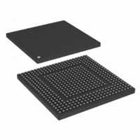
MPC8308VMAGD Freescale Semiconductor, MPC8308VMAGD Datasheet - Page 1097

MPC8308VMAGD
Manufacturer Part Number
MPC8308VMAGD
Description
MPU POWERQUICC II PRO 473MAPBGA
Manufacturer
Freescale Semiconductor
Datasheets
1.MPC8308VMAGD.pdf
(90 pages)
2.MPC8308VMAGD.pdf
(2 pages)
3.MPC8308VMAGD.pdf
(1170 pages)
4.MPC8308VMAGD.pdf
(14 pages)
Specifications of MPC8308VMAGD
Processor Type
MPC83xx PowerQUICC II Pro 32-Bit
Speed
400MHz
Voltage
1V
Mounting Type
Surface Mount
Package / Case
473-MAPBGA
Product
Network Processor
Data Rate
256 bps
Frequency
400 MHz
Supply Voltage (max)
3.6 V
Supply Voltage (min)
3 V
Supply Current (max)
5 uA
Maximum Operating Temperature
+ 105 C
Minimum Operating Temperature
0 C
Interface
I2C, JTAG, SPI
Mounting Style
SMD/SMT
Lead Free Status / RoHS Status
Lead free / RoHS Compliant
Features
-
Lead Free Status / Rohs Status
Lead free / RoHS Compliant
Available stocks
Company
Part Number
Manufacturer
Quantity
Price
Company:
Part Number:
MPC8308VMAGD
Manufacturer:
FREESCAL
Quantity:
300
Company:
Part Number:
MPC8308VMAGD
Manufacturer:
Freescale Semiconductor
Quantity:
10 000
Part Number:
MPC8308VMAGD
Manufacturer:
FREESCALE
Quantity:
20 000
Company:
Part Number:
MPC8308VMAGD400/266
Manufacturer:
FREESCAL
Quantity:
300
Company:
Part Number:
MPC8308VMAGDA
Manufacturer:
Freescale Semiconductor
Quantity:
10 000
- MPC8308VMAGD PDF datasheet
- MPC8308VMAGD PDF datasheet #2
- MPC8308VMAGD PDF datasheet #3
- MPC8308VMAGD PDF datasheet #4
- Current page: 1097 of 1170
- Download datasheet (9Mb)
Figure 18-7
Table 18-10
The bits contained in the UIIR registers are described in
18.3.1.6
UFCR is used to enable and clear the receiver and transmitter FIFOs, set a receiver FIFO trigger level to
control the received data available interrupt, and select the type of DMA signaling.
Freescale Semiconductor
Offset: 0x0_4502, 0x0_4602
Bits
IID3–
0–1
2–3
5–6
0001
0110
0100
1100
0010
Reset
IID0
4
7
W
R
IID2–IID1
Priority
Highest
Second
Second
Name
Level
Third
IID3
IID0
FE
—
—
shows the bits in the UIIR.
describes the fields of the UIIR.
0
0
FIFO Control Registers (UFCR1 and UFCR2)
Received data available Receiver data available or trigger level
FE
FIFOs enabled. Reflects the setting of UFCR[FEN].
Reserved
Interrupt ID bits identify the highest priority interrupt that is pending as indicated in
set along with IID2 only when a time out interrupt is pending for FIFO mode.
Interrupt ID bits identify the highest priority pending interrupt as indicated in
IID0 indicates when an interrupt is pending.
0 The UART has an active interrupt ready to be serviced.
1 No interrupt is pending.
Receiver line status
Character time-out
Interrupt Type
UTHR empty
MPC8308 PowerQUICC II Pro Processor Reference Manual, Rev. 0
0
1
Figure 18-7. Interrupt ID Registers (UIIR1 and UIIR2)
—
Table 18-10. UIIR Field Descriptions
Table 18-11. UIIR IID Bits Summary
0
2
Overrun error, parity error, framing error, or
break interrupt
reached in FIFO mode.
No characters were removed from or input to
the receiver FIFO during the last four
character times and at least one character is
in the receiver FIFO.
Transmitter holding register is empty.
—
Interrupt Description
0
3
Description
Table
—
IID3
0
4
18-11.
IID2
5
0
Reading the line status register
Reading the receiver buffer
register or if the number of
bytes in the receiver FIFO
drops below the trigger level.
Reading the receiver buffer
register
Reading UIIR or writing to
UTHR
Table
How To Reset Interrupt
IID1
Access: User read-only
0
18-11.
6
Table
—
18-11. IID3 is
IID0
1
7
DUART
18-9
Related parts for MPC8308VMAGD
Image
Part Number
Description
Manufacturer
Datasheet
Request
R
Part Number:
Description:
Development Boards & Kits - Other Processors MPC8308-NSG
Manufacturer:
Freescale Semiconductor
Datasheet:

Part Number:
Description:
MCU, MPU & DSP Development Tools For MPC8308 Ethernet USB I2C SPI
Manufacturer:
Freescale Semiconductor
Datasheet:

Part Number:
Description:
MCU, MPU & DSP Development Tools For MPC8308 Ethernet USB 32bit
Manufacturer:
Freescale Semiconductor
Datasheet:
Part Number:
Description:
Mpc8308 Powerquicc Ii Pro Processor Hardware Specification
Manufacturer:
Freescale Semiconductor, Inc
Datasheet:

Part Number:
Description:
BOARD REF DESIGN MPC8308
Manufacturer:
Freescale Semiconductor
Datasheet:

Part Number:
Description:
MPC8308 PowerQUICC II Pro Processor Hardware Specification
Manufacturer:
FREESCALE [Freescale Semiconductor, Inc]
Datasheet:
Part Number:
Description:
Microprocessors - MPU E300 ext tmp Qual266
Manufacturer:
Freescale Semiconductor
Datasheet:
Part Number:
Description:
Microprocessors - MPU E300 ext tmp Qual333
Manufacturer:
Freescale Semiconductor
Datasheet:
Part Number:
Description:
Microprocessors - MPU E300 EXT TEMP PB 400
Manufacturer:
Freescale Semiconductor
Datasheet:
Part Number:
Description:
Microprocessors - MPU E300 MP Pb 266
Manufacturer:
Freescale Semiconductor
Datasheet:
Part Number:
Description:
Microprocessors - MPU E300 MP Pb 400
Manufacturer:
Freescale Semiconductor
Datasheet:
Part Number:
Description:
Microprocessors - MPU E300 MP Pb 333
Manufacturer:
Freescale Semiconductor
Datasheet:
Part Number:
Description:
Manufacturer:
Freescale Semiconductor, Inc
Datasheet:
Part Number:
Description:
Manufacturer:
Freescale Semiconductor, Inc
Datasheet:
Part Number:
Description:
Manufacturer:
Freescale Semiconductor, Inc
Datasheet:


