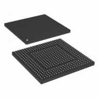
MPC8308VMAGD Freescale Semiconductor, MPC8308VMAGD Datasheet - Page 113

MPC8308VMAGD
Manufacturer Part Number
MPC8308VMAGD
Description
MPU POWERQUICC II PRO 473MAPBGA
Manufacturer
Freescale Semiconductor
Datasheets
1.MPC8308VMAGD.pdf
(90 pages)
2.MPC8308VMAGD.pdf
(2 pages)
3.MPC8308VMAGD.pdf
(1170 pages)
4.MPC8308VMAGD.pdf
(14 pages)
Specifications of MPC8308VMAGD
Processor Type
MPC83xx PowerQUICC II Pro 32-Bit
Speed
400MHz
Voltage
1V
Mounting Type
Surface Mount
Package / Case
473-MAPBGA
Product
Network Processor
Data Rate
256 bps
Frequency
400 MHz
Supply Voltage (max)
3.6 V
Supply Voltage (min)
3 V
Supply Current (max)
5 uA
Maximum Operating Temperature
+ 105 C
Minimum Operating Temperature
0 C
Interface
I2C, JTAG, SPI
Mounting Style
SMD/SMT
Lead Free Status / RoHS Status
Lead free / RoHS Compliant
Features
-
Lead Free Status / Rohs Status
Lead free / RoHS Compliant
Available stocks
Company
Part Number
Manufacturer
Quantity
Price
Company:
Part Number:
MPC8308VMAGD
Manufacturer:
FREESCAL
Quantity:
300
Company:
Part Number:
MPC8308VMAGD
Manufacturer:
Freescale Semiconductor
Quantity:
10 000
Part Number:
MPC8308VMAGD
Manufacturer:
FREESCALE
Quantity:
20 000
Company:
Part Number:
MPC8308VMAGD400/266
Manufacturer:
FREESCAL
Quantity:
300
Company:
Part Number:
MPC8308VMAGDA
Manufacturer:
Freescale Semiconductor
Quantity:
10 000
- MPC8308VMAGD PDF datasheet
- MPC8308VMAGD PDF datasheet #2
- MPC8308VMAGD PDF datasheet #3
- MPC8308VMAGD PDF datasheet #4
- Current page: 113 of 1170
- Download datasheet (9Mb)
4.2.2
Assertion of the PORESET external signal initiates the power-on reset flow. PORESET should be asserted
externally for at least 32 input clock cycles after stable external power to the device is applied.
Directly after the negation of PORESET, the device starts the configuration process. The device asserts
HRESET throughout the power-on reset process, including configuration. Configuration time varies
according to the configuration source and SYS_CLK_IN frequency. Initially, the reset configuration inputs
are sampled to determine the configuration source. Next, the device starts loading the reset configuration
words. The system PLL begins to lock according to the clock mode values in the reset configuration word
low. When the system PLL is locked, the clock unit starts distributing clock signals in the device. At this
stage, the core PLL begins to lock. When it is locked and the reset configuration words are loaded,
HRESET is released.
The detailed power-on reset (POR) flow for the device is as follows:
The device is now in its ready state.
Freescale Semiconductor
1. Power is applied to meet the specifications in the device data sheet.
2. The system asserts PORESET and TRST, causing all registers to be initialized to their default states
3. The system applies a stable SYS_CLK_IN signal and stable reset configuration inputs
4. The system negates PORESET after at least 32 stable SYS_CLK_IN clock cycles.
5. The device samples the reset configuration input signals to determine the reset configuration words
6. The device starts loading the reset configuration words.
7. When the reset configuration word low is loaded, the system PLL begins to lock.
8. The core PLL begins to lock.
9. The device drives HRESET asserted until the e300 PLL is locked and the reset configuration words
10. The user optionally negates HRESET if it was not negated earlier.
11. The internal reset to the core and the rest of the logic is negated. I/O drivers are enabled.
12. The device stops driving HRESET. The reset to the e300 core is negated and the core is enabled.
13. If the e300 core is required to proceed, the boot sequencer should enable boot vector fetch by
14. The boot vector fetch by the core can proceed, if enabled.
and most I/O drivers to be released to high-impedance.
(CFG_RESET_SOURCE).
source.
Loading time depends on the reset configuration word source.
When the system PLL is locked, csb_clk is supplied to the core PLL.
are loaded.
JTAG logic must always be initialized by asserting TRST. If the JTAG signals are not used, TRST
should be connected directly to PORESET. TRST must not remain asserted after the negation of
PORESET.
The boot sequencer, if enabled, is released, causing it to load configuration data from serial ROMs,
as described in
clearing ACR[COREDIS] as described in
Power-On Reset Flow
Section 17.4.5, “Boot Sequencer Mode.”
MPC8308 PowerQUICC II Pro Processor Reference Manual, Rev. 0
Section 6.2.1, “Arbiter Configuration Register (ACR).”
Reset, Clocking, and Initialization
4-5
Related parts for MPC8308VMAGD
Image
Part Number
Description
Manufacturer
Datasheet
Request
R
Part Number:
Description:
Development Boards & Kits - Other Processors MPC8308-NSG
Manufacturer:
Freescale Semiconductor
Datasheet:

Part Number:
Description:
MCU, MPU & DSP Development Tools For MPC8308 Ethernet USB I2C SPI
Manufacturer:
Freescale Semiconductor
Datasheet:

Part Number:
Description:
MCU, MPU & DSP Development Tools For MPC8308 Ethernet USB 32bit
Manufacturer:
Freescale Semiconductor
Datasheet:
Part Number:
Description:
Mpc8308 Powerquicc Ii Pro Processor Hardware Specification
Manufacturer:
Freescale Semiconductor, Inc
Datasheet:

Part Number:
Description:
BOARD REF DESIGN MPC8308
Manufacturer:
Freescale Semiconductor
Datasheet:

Part Number:
Description:
MPC8308 PowerQUICC II Pro Processor Hardware Specification
Manufacturer:
FREESCALE [Freescale Semiconductor, Inc]
Datasheet:
Part Number:
Description:
Microprocessors - MPU E300 ext tmp Qual266
Manufacturer:
Freescale Semiconductor
Datasheet:
Part Number:
Description:
Microprocessors - MPU E300 ext tmp Qual333
Manufacturer:
Freescale Semiconductor
Datasheet:
Part Number:
Description:
Microprocessors - MPU E300 EXT TEMP PB 400
Manufacturer:
Freescale Semiconductor
Datasheet:
Part Number:
Description:
Microprocessors - MPU E300 MP Pb 266
Manufacturer:
Freescale Semiconductor
Datasheet:
Part Number:
Description:
Microprocessors - MPU E300 MP Pb 400
Manufacturer:
Freescale Semiconductor
Datasheet:
Part Number:
Description:
Microprocessors - MPU E300 MP Pb 333
Manufacturer:
Freescale Semiconductor
Datasheet:
Part Number:
Description:
Manufacturer:
Freescale Semiconductor, Inc
Datasheet:
Part Number:
Description:
Manufacturer:
Freescale Semiconductor, Inc
Datasheet:
Part Number:
Description:
Manufacturer:
Freescale Semiconductor, Inc
Datasheet:


