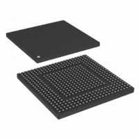
MPC8308VMAGD Freescale Semiconductor, MPC8308VMAGD Datasheet - Page 582

MPC8308VMAGD
Manufacturer Part Number
MPC8308VMAGD
Description
MPU POWERQUICC II PRO 473MAPBGA
Manufacturer
Freescale Semiconductor
Datasheets
1.MPC8308VMAGD.pdf
(90 pages)
2.MPC8308VMAGD.pdf
(2 pages)
3.MPC8308VMAGD.pdf
(1170 pages)
4.MPC8308VMAGD.pdf
(14 pages)
Specifications of MPC8308VMAGD
Processor Type
MPC83xx PowerQUICC II Pro 32-Bit
Speed
400MHz
Voltage
1V
Mounting Type
Surface Mount
Package / Case
473-MAPBGA
Product
Network Processor
Data Rate
256 bps
Frequency
400 MHz
Supply Voltage (max)
3.6 V
Supply Voltage (min)
3 V
Supply Current (max)
5 uA
Maximum Operating Temperature
+ 105 C
Minimum Operating Temperature
0 C
Interface
I2C, JTAG, SPI
Mounting Style
SMD/SMT
Lead Free Status / RoHS Status
Lead free / RoHS Compliant
Features
-
Lead Free Status / Rohs Status
Lead free / RoHS Compliant
Available stocks
Company
Part Number
Manufacturer
Quantity
Price
Company:
Part Number:
MPC8308VMAGD
Manufacturer:
FREESCAL
Quantity:
300
Company:
Part Number:
MPC8308VMAGD
Manufacturer:
Freescale Semiconductor
Quantity:
10 000
Part Number:
MPC8308VMAGD
Manufacturer:
FREESCALE
Quantity:
20 000
Company:
Part Number:
MPC8308VMAGD400/266
Manufacturer:
FREESCAL
Quantity:
300
Company:
Part Number:
MPC8308VMAGDA
Manufacturer:
Freescale Semiconductor
Quantity:
10 000
- MPC8308VMAGD PDF datasheet
- MPC8308VMAGD PDF datasheet #2
- MPC8308VMAGD PDF datasheet #3
- MPC8308VMAGD PDF datasheet #4
- Current page: 582 of 1170
- Download datasheet (9Mb)
Universal Serial Bus Interface
13.3
This section provides the memory map and detailed descriptions of all USB interface registers. The
memory map of the USB interface is shown in
13-4
0x000–0x0FF
USBDR_TXDRXD[0:7]
USBDR_PWR_FAULT
Offset
USBDR_PCTL0
USBDR_PCTL1
USBDR_STP
USBDR_CLK
Signal
Memory Map/Register Definitions
Reserved, should be cleared
MPC8308 PowerQUICC II Pro Processor Reference Manual, Rev. 0
I/O
I/O Data bit n . USBDR_TXDRXD n is bit n of the 8-bit (USBDR_TXDRXD7–USBDR_TXDRXD0),
O Stop. USBDR_STP indicates the end of a transfer on the bus.
O Port control 0. USBDR_PCTL0 controls the port status indicator LED 0 when in host mode.
O Port control 1. USBDR_PCTL1 controls the port status indicator LED 1 when in host mode.
I
I
Vbus.
uni-directional data bus used to carry USB, register, and interrupt data between the PHY and
the USB controller.
Clocking signal for ULPI PHY interface.
Power fault. USBDR_PWR_FAULT indicates whether a power fault occurred on the USB port
Meaning
Meaning
Meaning
Meaning
Meaning
Timing
Timing
Table 13-2. ULPI Signal Descriptions (continued)
Timing Synchronous to PHY_CLK.
Timing Synchronous to PHY_CLK.
Timing Synchronous to PHY_CLK.
USB DR Controller—Block Base Address 0x2_3000
State
State
State
State
State
Table 13-3. USB Interface Memory Map
Register
Asserted—USB asserts this signal for 1 clock cycle to stop the data stream
Negated—Indicates normal operation.
Asserted—Indicates that a Vbus fault occurred. Applications that support power
Negated—Indicates normal operation.
Asserted—LED on.
Negated—LED off.
Synchronous to PHY_CLK.
Asserted—LED on.
Negated—LED off.
Synchronous to PHY_CLK.
Asserted—Data bit n is 1.
Negated—Data bit n is 0.
USB DR Controller Registers
currently on the bus. If USB port is sending data to the PHY, USBDR_STP
indicates the last byte of data was previously on the bus. If the PHY is
sending data to USB port, USBDR_STP forces the PHY to end its transfer,
negate USBDR_DIR and relinquish control of the data bus to the USB port.
switching must shut down Vbus power.
Table
13-3.
Description
Access
—
Reset
—
Freescale Semiconductor
Section/Page
—
Related parts for MPC8308VMAGD
Image
Part Number
Description
Manufacturer
Datasheet
Request
R
Part Number:
Description:
Development Boards & Kits - Other Processors MPC8308-NSG
Manufacturer:
Freescale Semiconductor
Datasheet:

Part Number:
Description:
MCU, MPU & DSP Development Tools For MPC8308 Ethernet USB I2C SPI
Manufacturer:
Freescale Semiconductor
Datasheet:

Part Number:
Description:
MCU, MPU & DSP Development Tools For MPC8308 Ethernet USB 32bit
Manufacturer:
Freescale Semiconductor
Datasheet:
Part Number:
Description:
Mpc8308 Powerquicc Ii Pro Processor Hardware Specification
Manufacturer:
Freescale Semiconductor, Inc
Datasheet:

Part Number:
Description:
BOARD REF DESIGN MPC8308
Manufacturer:
Freescale Semiconductor
Datasheet:

Part Number:
Description:
MPC8308 PowerQUICC II Pro Processor Hardware Specification
Manufacturer:
FREESCALE [Freescale Semiconductor, Inc]
Datasheet:
Part Number:
Description:
Microprocessors - MPU E300 ext tmp Qual266
Manufacturer:
Freescale Semiconductor
Datasheet:
Part Number:
Description:
Microprocessors - MPU E300 ext tmp Qual333
Manufacturer:
Freescale Semiconductor
Datasheet:
Part Number:
Description:
Microprocessors - MPU E300 EXT TEMP PB 400
Manufacturer:
Freescale Semiconductor
Datasheet:
Part Number:
Description:
Microprocessors - MPU E300 MP Pb 266
Manufacturer:
Freescale Semiconductor
Datasheet:
Part Number:
Description:
Microprocessors - MPU E300 MP Pb 400
Manufacturer:
Freescale Semiconductor
Datasheet:
Part Number:
Description:
Microprocessors - MPU E300 MP Pb 333
Manufacturer:
Freescale Semiconductor
Datasheet:
Part Number:
Description:
Manufacturer:
Freescale Semiconductor, Inc
Datasheet:
Part Number:
Description:
Manufacturer:
Freescale Semiconductor, Inc
Datasheet:
Part Number:
Description:
Manufacturer:
Freescale Semiconductor, Inc
Datasheet:


