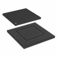
MPC8308VMAGD Freescale Semiconductor, MPC8308VMAGD Datasheet - Page 589

MPC8308VMAGD
Manufacturer Part Number
MPC8308VMAGD
Description
MPU POWERQUICC II PRO 473MAPBGA
Manufacturer
Freescale Semiconductor
Datasheets
1.MPC8308VMAGD.pdf
(90 pages)
2.MPC8308VMAGD.pdf
(2 pages)
3.MPC8308VMAGD.pdf
(1170 pages)
4.MPC8308VMAGD.pdf
(14 pages)
Specifications of MPC8308VMAGD
Processor Type
MPC83xx PowerQUICC II Pro 32-Bit
Speed
400MHz
Voltage
1V
Mounting Type
Surface Mount
Package / Case
473-MAPBGA
Product
Network Processor
Data Rate
256 bps
Frequency
400 MHz
Supply Voltage (max)
3.6 V
Supply Voltage (min)
3 V
Supply Current (max)
5 uA
Maximum Operating Temperature
+ 105 C
Minimum Operating Temperature
0 C
Interface
I2C, JTAG, SPI
Mounting Style
SMD/SMT
Lead Free Status / RoHS Status
Lead free / RoHS Compliant
Features
-
Lead Free Status / Rohs Status
Lead free / RoHS Compliant
Available stocks
Company
Part Number
Manufacturer
Quantity
Price
Company:
Part Number:
MPC8308VMAGD
Manufacturer:
FREESCAL
Quantity:
300
Company:
Part Number:
MPC8308VMAGD
Manufacturer:
Freescale Semiconductor
Quantity:
10 000
Part Number:
MPC8308VMAGD
Manufacturer:
FREESCALE
Quantity:
20 000
Company:
Part Number:
MPC8308VMAGD400/266
Manufacturer:
FREESCAL
Quantity:
300
Company:
Part Number:
MPC8308VMAGDA
Manufacturer:
Freescale Semiconductor
Quantity:
10 000
- MPC8308VMAGD PDF datasheet
- MPC8308VMAGD PDF datasheet #2
- MPC8308VMAGD PDF datasheet #3
- MPC8308VMAGD PDF datasheet #4
- Current page: 589 of 1170
- Download datasheet (9Mb)
Table 13-10
Freescale Semiconductor
31–24
23–16
Bits
9–8
15
14
13
12
11
10
7
6
ATDTW Add dTD TripWire. This is a non-EHCI bit. Used as a semaphore when a dTD is added to an active (primed)
SUTW
Name
ASPE
ASP
FS2
ITC
IAA
LR
—
—
—
provides bit descriptions for the USBCMD register.
Reserved, should be cleared.
Interrupt threshold control. The system software uses this field to set the maximum rate at which the USB
DR module issues interrupts. ITC contains the maximum interrupt interval measured in microframes. Valid
values are shown below.
0x00 Immediate (no threshold)
0x01 1 microframe
0x02 2 microframes
0x04 4 microframes
0x08 8 microframes
0x10 16 microframes
0x20 32 microframes
0x40 40 microframes
See bits 3–2 below. This is a non-EHCI bit.
endpoint. This bit is set and cleared by software. This bit shall also be cleared by hardware when is state
machine is hazard region where adding a dTD to a primed endpoint may go unrecognized. More information
on the use of this bit is described in
Setup tripwire. This is a non-EHCI bit. Used as a semaphore when the 8 bytes of setup data read extracted
from a QH by the DCD. If the setup lockout mode is off (See USBMODE) then there exists a hazard when
new setup data arrives and the DCD is copying setup from the QH for a previous setup packet. This bit is
set and cleared by software and will be cleared by hardware when a hazard exists. More information on the
use of this bit is described in
Reserved, should be cleared.
Asynchronous schedule park mode enable. Software uses this bit to enable or disable park mode.
0 Disabled
1 Enabled
Reserved, should be cleared.
Asynchronous schedule park mode count. This field defaults to 0x3 and is R/W. It contains a count of the
number of successive transactions the host controller is allowed to execute from a high-speed queue head
on the Asynchronous schedule before continuing traversal of the Asynchronous schedule. Valid values are
0x1H to 0x3H. Software must not write a zero to this field when ASPE is set as this results in undefined
behavior.
Light host/device controller reset (OPTIONAL). Not implemented. Always 0.
Interrupt on async advance doorbell. Used as a doorbell by software to tell the USB DR controller to issue
an interrupt the next time it advances asynchronous schedule. Software must write a 1 to this bit to ring the
doorbell.
When the controller has evicted all appropriate cached schedule states, it sets USBSTS[AAI]. If
USBINTR[AAE] is set, the host controller asserts an interrupt at the next interrupt threshold.
The controller clears this bit after it has set USBSTS[AAI]. Software should not set this bit when the
asynchronous schedule is inactive. Doing so yields undefined results.
This bit is only used in host mode. Setting this bit when the USB DR module is in device mode is selected
results in undefined results.
MPC8308 PowerQUICC II Pro Processor Reference Manual, Rev. 0
Table 13-10. USBCMD Register Field Descriptions
Section 13.9.2, “Device Operation.”
Section 13.9.2, “Device Operation.”
Description
Universal Serial Bus Interface
13-11
Related parts for MPC8308VMAGD
Image
Part Number
Description
Manufacturer
Datasheet
Request
R
Part Number:
Description:
Development Boards & Kits - Other Processors MPC8308-NSG
Manufacturer:
Freescale Semiconductor
Datasheet:

Part Number:
Description:
MCU, MPU & DSP Development Tools For MPC8308 Ethernet USB I2C SPI
Manufacturer:
Freescale Semiconductor
Datasheet:

Part Number:
Description:
MCU, MPU & DSP Development Tools For MPC8308 Ethernet USB 32bit
Manufacturer:
Freescale Semiconductor
Datasheet:
Part Number:
Description:
Mpc8308 Powerquicc Ii Pro Processor Hardware Specification
Manufacturer:
Freescale Semiconductor, Inc
Datasheet:

Part Number:
Description:
BOARD REF DESIGN MPC8308
Manufacturer:
Freescale Semiconductor
Datasheet:

Part Number:
Description:
MPC8308 PowerQUICC II Pro Processor Hardware Specification
Manufacturer:
FREESCALE [Freescale Semiconductor, Inc]
Datasheet:
Part Number:
Description:
Microprocessors - MPU E300 ext tmp Qual266
Manufacturer:
Freescale Semiconductor
Datasheet:
Part Number:
Description:
Microprocessors - MPU E300 ext tmp Qual333
Manufacturer:
Freescale Semiconductor
Datasheet:
Part Number:
Description:
Microprocessors - MPU E300 EXT TEMP PB 400
Manufacturer:
Freescale Semiconductor
Datasheet:
Part Number:
Description:
Microprocessors - MPU E300 MP Pb 266
Manufacturer:
Freescale Semiconductor
Datasheet:
Part Number:
Description:
Microprocessors - MPU E300 MP Pb 400
Manufacturer:
Freescale Semiconductor
Datasheet:
Part Number:
Description:
Microprocessors - MPU E300 MP Pb 333
Manufacturer:
Freescale Semiconductor
Datasheet:
Part Number:
Description:
Manufacturer:
Freescale Semiconductor, Inc
Datasheet:
Part Number:
Description:
Manufacturer:
Freescale Semiconductor, Inc
Datasheet:
Part Number:
Description:
Manufacturer:
Freescale Semiconductor, Inc
Datasheet:


