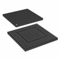
MPC8308VMAGD Freescale Semiconductor, MPC8308VMAGD Datasheet - Page 35

MPC8308VMAGD
Manufacturer Part Number
MPC8308VMAGD
Description
MPU POWERQUICC II PRO 473MAPBGA
Manufacturer
Freescale Semiconductor
Datasheets
1.MPC8308VMAGD.pdf
(90 pages)
2.MPC8308VMAGD.pdf
(2 pages)
3.MPC8308VMAGD.pdf
(1170 pages)
4.MPC8308VMAGD.pdf
(14 pages)
Specifications of MPC8308VMAGD
Processor Type
MPC83xx PowerQUICC II Pro 32-Bit
Speed
400MHz
Voltage
1V
Mounting Type
Surface Mount
Package / Case
473-MAPBGA
Product
Network Processor
Data Rate
256 bps
Frequency
400 MHz
Supply Voltage (max)
3.6 V
Supply Voltage (min)
3 V
Supply Current (max)
5 uA
Maximum Operating Temperature
+ 105 C
Minimum Operating Temperature
0 C
Interface
I2C, JTAG, SPI
Mounting Style
SMD/SMT
Lead Free Status / RoHS Status
Lead free / RoHS Compliant
Features
-
Lead Free Status / Rohs Status
Lead free / RoHS Compliant
Available stocks
Company
Part Number
Manufacturer
Quantity
Price
Company:
Part Number:
MPC8308VMAGD
Manufacturer:
FREESCAL
Quantity:
300
Company:
Part Number:
MPC8308VMAGD
Manufacturer:
Freescale Semiconductor
Quantity:
10 000
Part Number:
MPC8308VMAGD
Manufacturer:
FREESCALE
Quantity:
20 000
Company:
Part Number:
MPC8308VMAGD400/266
Manufacturer:
FREESCAL
Quantity:
300
Company:
Part Number:
MPC8308VMAGDA
Manufacturer:
Freescale Semiconductor
Quantity:
10 000
- MPC8308VMAGD PDF datasheet
- MPC8308VMAGD PDF datasheet #2
- MPC8308VMAGD PDF datasheet #3
- MPC8308VMAGD PDF datasheet #4
- Current page: 35 of 1170
- Download datasheet (9Mb)
Figure
Number
16-115
16-116
16-117
16-118
16-119
16-120
16-121
16-122
16-123
16-124
16-125
16-126
16-127
16-128
16-129
16-130
16-131
16-132
16-133
16-134
16-135
17-1
17-2
17-3
17-4
17-5
17-6
17-7
17-8
17-9
17-10
17-11
18-1
18-2
18-3
18-4
18-5
18-6
18-7
18-8
18-9
Freescale Semiconductor
TMR_FIPERn Register Definition ................................................................................... 16-120
TMR_ETTS1-2_H/L Register Definition ......................................................................... 16-120
eTSEC-MII Connection .................................................................................................... 16-121
eTSEC-RGMII Connection............................................................................................... 16-122
Definition of Custom Preamble Sequence ........................................................................ 16-129
Definition of Received Preamble Sequence...................................................................... 16-129
Ethernet Address Recognition Flowchart ......................................................................... 16-131
Location of Frame Control Blocks for TOE Parameters .................................................. 16-140
Transmit Frame Control Block ......................................................................................... 16-141
Receive Frame Control Block........................................................................................... 16-142
Structure of the Receive Queue Filer Table ...................................................................... 16-147
1588 Timer Design Partition ............................................................................................. 16-158
Ethernet Sampling Points for 1588 ................................................................................... 16-158
PTP Packet Format............................................................................................................ 16-160
Buffer Format for Transmit Time-Stamp Insertion........................................................... 16-162
Transmit Frame Control Block ......................................................................................... 16-162
Example of eTSEC Memory Structure for BDs ............................................................... 16-165
Buffer Descriptor Ring...................................................................................................... 16-165
Transmit Buffer Descriptor ............................................................................................... 16-166
Receive Buffer Descriptor................................................................................................. 16-169
Mapping of RxBDs to a C Data Structure ........................................................................ 16-170
I
I
I
I
I
I
I
I
EEPROM Contents ............................................................................................................. 17-19
EEPROM Data Format for One Register Preload Command............................................. 17-20
Example I
UART Block Diagram .......................................................................................................... 18-1
Receiver Buffer Registers (URBR1 and URBR2) ................................................................ 18-5
Transmitter Holding Registers (UTHR1 and UTHR2) ......................................................... 18-6
Divisor Most Significant Byte Registers (UDMB1 and UDMB2) ....................................... 18-6
Divisor Least Significant Byte Registers (UDLB1 and UDLB2)......................................... 18-7
Interrupt Enable Registers (UIER1 and UIER2)................................................................... 18-8
Interrupt ID Registers (UIIR1 and UIIR2)............................................................................ 18-9
FIFO Control Registers (UFCR1 and UFCR2)................................................................... 18-10
Line Control Register (ULCR1 and ULCR2) ..................................................................... 18-11
2
2
2
2
2
2
2
2
C Block Diagram................................................................................................................ 17-1
C Address Register (I2CADR)........................................................................................... 17-5
C Frequency Divider Register (I2CFDR) .......................................................................... 17-5
C Control Register (I2CCR)............................................................................................... 17-6
C Status Register (I2CSR) ................................................................................................. 17-8
C Data Register (I2CDR) ................................................................................................... 17-9
C Digital Filter Sampling Rate Register (I2CDFSRR) .................................................... 17-10
C Interface Transaction Protocol...................................................................................... 17-11
2
C Interrupt Service Routine Flowchart ............................................................. 17-22
MPC8308 PowerQUICC II Pro Processor Reference Manual, Rev. 0
Figures
Title
Number
Page
xxxv
Related parts for MPC8308VMAGD
Image
Part Number
Description
Manufacturer
Datasheet
Request
R
Part Number:
Description:
Development Boards & Kits - Other Processors MPC8308-NSG
Manufacturer:
Freescale Semiconductor
Datasheet:

Part Number:
Description:
MCU, MPU & DSP Development Tools For MPC8308 Ethernet USB I2C SPI
Manufacturer:
Freescale Semiconductor
Datasheet:

Part Number:
Description:
MCU, MPU & DSP Development Tools For MPC8308 Ethernet USB 32bit
Manufacturer:
Freescale Semiconductor
Datasheet:
Part Number:
Description:
Mpc8308 Powerquicc Ii Pro Processor Hardware Specification
Manufacturer:
Freescale Semiconductor, Inc
Datasheet:

Part Number:
Description:
BOARD REF DESIGN MPC8308
Manufacturer:
Freescale Semiconductor
Datasheet:

Part Number:
Description:
MPC8308 PowerQUICC II Pro Processor Hardware Specification
Manufacturer:
FREESCALE [Freescale Semiconductor, Inc]
Datasheet:
Part Number:
Description:
Microprocessors - MPU E300 ext tmp Qual266
Manufacturer:
Freescale Semiconductor
Datasheet:
Part Number:
Description:
Microprocessors - MPU E300 ext tmp Qual333
Manufacturer:
Freescale Semiconductor
Datasheet:
Part Number:
Description:
Microprocessors - MPU E300 EXT TEMP PB 400
Manufacturer:
Freescale Semiconductor
Datasheet:
Part Number:
Description:
Microprocessors - MPU E300 MP Pb 266
Manufacturer:
Freescale Semiconductor
Datasheet:
Part Number:
Description:
Microprocessors - MPU E300 MP Pb 400
Manufacturer:
Freescale Semiconductor
Datasheet:
Part Number:
Description:
Microprocessors - MPU E300 MP Pb 333
Manufacturer:
Freescale Semiconductor
Datasheet:
Part Number:
Description:
Manufacturer:
Freescale Semiconductor, Inc
Datasheet:
Part Number:
Description:
Manufacturer:
Freescale Semiconductor, Inc
Datasheet:
Part Number:
Description:
Manufacturer:
Freescale Semiconductor, Inc
Datasheet:


