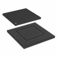
MPC8308VMAGD Freescale Semiconductor, MPC8308VMAGD Datasheet - Page 724

MPC8308VMAGD
Manufacturer Part Number
MPC8308VMAGD
Description
MPU POWERQUICC II PRO 473MAPBGA
Manufacturer
Freescale Semiconductor
Datasheets
1.MPC8308VMAGD.pdf
(90 pages)
2.MPC8308VMAGD.pdf
(2 pages)
3.MPC8308VMAGD.pdf
(1170 pages)
4.MPC8308VMAGD.pdf
(14 pages)
Specifications of MPC8308VMAGD
Processor Type
MPC83xx PowerQUICC II Pro 32-Bit
Speed
400MHz
Voltage
1V
Mounting Type
Surface Mount
Package / Case
473-MAPBGA
Product
Network Processor
Data Rate
256 bps
Frequency
400 MHz
Supply Voltage (max)
3.6 V
Supply Voltage (min)
3 V
Supply Current (max)
5 uA
Maximum Operating Temperature
+ 105 C
Minimum Operating Temperature
0 C
Interface
I2C, JTAG, SPI
Mounting Style
SMD/SMT
Lead Free Status / RoHS Status
Lead free / RoHS Compliant
Features
-
Lead Free Status / Rohs Status
Lead free / RoHS Compliant
Available stocks
Company
Part Number
Manufacturer
Quantity
Price
Company:
Part Number:
MPC8308VMAGD
Manufacturer:
FREESCAL
Quantity:
300
Company:
Part Number:
MPC8308VMAGD
Manufacturer:
Freescale Semiconductor
Quantity:
10 000
Part Number:
MPC8308VMAGD
Manufacturer:
FREESCALE
Quantity:
20 000
Company:
Part Number:
MPC8308VMAGD400/266
Manufacturer:
FREESCAL
Quantity:
300
Company:
Part Number:
MPC8308VMAGDA
Manufacturer:
Freescale Semiconductor
Quantity:
10 000
- MPC8308VMAGD PDF datasheet
- MPC8308VMAGD PDF datasheet #2
- MPC8308VMAGD PDF datasheet #3
- MPC8308VMAGD PDF datasheet #4
- Current page: 724 of 1170
- Download datasheet (9Mb)
Universal Serial Bus Interface
Allocate 8-DWord dTD block of memory aligned to 8-DWord boundaries. Example: bit address 4–0 would
be equal to ‘00000’.
Write the following fields:
13.8.5.3
To safely add a dTD, the DCD must account for the event in which the device controller reaches the end
of the dTD list at the same time a new dTD is being added to the end of the list.
First, determine whether the link list is empty by checking the DCD driver to see if the pipe is empty
(internal representation of linked-list should indicate if any packets are outstanding). Then follow the
sequence of actions in the following list as appropriate, depending on whether the link list is empty or not
empty.
13.8.5.4
After a dTD has been initialized and the associated endpoint primed the device controller will execute the
transfer upon the host-initiated request. The DCD is notified with a USB interrupt if the Interrupt On
13-146
1. Initialize first seven DWords to ‘0’.
2. Set the terminate bit to ‘1’.
3. Fill in total bytes with transfer size.
4. Set the interrupt on complete if desired.
5. Initialize the status field with the active bit set to ‘1’ and all remaining status bits set to ‘0’.
6. Fill in buffer pointer page 0 and the current offset to point to the start of the data buffer.
7. Initialize buffer pointer page 1 through page 4 to be one greater than each of the previous buffer
•
•
pointer.
Link list is empty
a) Write dQH next pointer AND dQH terminate bit to ‘0’ as a single DWord operation.
b) Clear active and halt bit in dQH (in case set from a previous error).
c) Prime endpoint by writing ‘1’ to correct bit position in ENDPTPRIME.
Link list is not empty
a) Add dTD to end of linked list.
b) Read correct prime bit in ENDPTPRIME—if ‘1’ DONE.
c) Set ATDTW bit in USBCMD register to ‘1’.
d) Read correct status bit in ENDPTSTATUS. (store in tmp. variable for later).
e) Read ATDTW bit in USBCMD register.
f) Write ATDTW bit in USBCMD register to ‘0’.
g) If status bit read in (3) is ‘1’ DONE.
h) If status bit read in (3) is ‘0’ then Goto Case 1: Step 1.
If ‘0’ goto 3.
If ‘1’ continue to 6.
Executing a Transfer Descriptor
Transfer Completion
MPC8308 PowerQUICC II Pro Processor Reference Manual, Rev. 0
Freescale Semiconductor
Related parts for MPC8308VMAGD
Image
Part Number
Description
Manufacturer
Datasheet
Request
R
Part Number:
Description:
Development Boards & Kits - Other Processors MPC8308-NSG
Manufacturer:
Freescale Semiconductor
Datasheet:

Part Number:
Description:
MCU, MPU & DSP Development Tools For MPC8308 Ethernet USB I2C SPI
Manufacturer:
Freescale Semiconductor
Datasheet:

Part Number:
Description:
MCU, MPU & DSP Development Tools For MPC8308 Ethernet USB 32bit
Manufacturer:
Freescale Semiconductor
Datasheet:
Part Number:
Description:
Mpc8308 Powerquicc Ii Pro Processor Hardware Specification
Manufacturer:
Freescale Semiconductor, Inc
Datasheet:

Part Number:
Description:
BOARD REF DESIGN MPC8308
Manufacturer:
Freescale Semiconductor
Datasheet:

Part Number:
Description:
MPC8308 PowerQUICC II Pro Processor Hardware Specification
Manufacturer:
FREESCALE [Freescale Semiconductor, Inc]
Datasheet:
Part Number:
Description:
Microprocessors - MPU E300 ext tmp Qual266
Manufacturer:
Freescale Semiconductor
Datasheet:
Part Number:
Description:
Microprocessors - MPU E300 ext tmp Qual333
Manufacturer:
Freescale Semiconductor
Datasheet:
Part Number:
Description:
Microprocessors - MPU E300 EXT TEMP PB 400
Manufacturer:
Freescale Semiconductor
Datasheet:
Part Number:
Description:
Microprocessors - MPU E300 MP Pb 266
Manufacturer:
Freescale Semiconductor
Datasheet:
Part Number:
Description:
Microprocessors - MPU E300 MP Pb 400
Manufacturer:
Freescale Semiconductor
Datasheet:
Part Number:
Description:
Microprocessors - MPU E300 MP Pb 333
Manufacturer:
Freescale Semiconductor
Datasheet:
Part Number:
Description:
Manufacturer:
Freescale Semiconductor, Inc
Datasheet:
Part Number:
Description:
Manufacturer:
Freescale Semiconductor, Inc
Datasheet:
Part Number:
Description:
Manufacturer:
Freescale Semiconductor, Inc
Datasheet:


