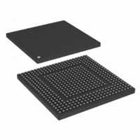
MPC8308VMAGD Freescale Semiconductor, MPC8308VMAGD Datasheet - Page 122

MPC8308VMAGD
Manufacturer Part Number
MPC8308VMAGD
Description
MPU POWERQUICC II PRO 473MAPBGA
Manufacturer
Freescale Semiconductor
Datasheets
1.MPC8308VMAGD.pdf
(90 pages)
2.MPC8308VMAGD.pdf
(2 pages)
3.MPC8308VMAGD.pdf
(1170 pages)
4.MPC8308VMAGD.pdf
(14 pages)
Specifications of MPC8308VMAGD
Processor Type
MPC83xx PowerQUICC II Pro 32-Bit
Speed
400MHz
Voltage
1V
Mounting Type
Surface Mount
Package / Case
473-MAPBGA
Product
Network Processor
Data Rate
256 bps
Frequency
400 MHz
Supply Voltage (max)
3.6 V
Supply Voltage (min)
3 V
Supply Current (max)
5 uA
Maximum Operating Temperature
+ 105 C
Minimum Operating Temperature
0 C
Interface
I2C, JTAG, SPI
Mounting Style
SMD/SMT
Lead Free Status / RoHS Status
Lead free / RoHS Compliant
Features
-
Lead Free Status / Rohs Status
Lead free / RoHS Compliant
Available stocks
Company
Part Number
Manufacturer
Quantity
Price
Company:
Part Number:
MPC8308VMAGD
Manufacturer:
FREESCAL
Quantity:
300
Company:
Part Number:
MPC8308VMAGD
Manufacturer:
Freescale Semiconductor
Quantity:
10 000
Part Number:
MPC8308VMAGD
Manufacturer:
FREESCALE
Quantity:
20 000
Company:
Part Number:
MPC8308VMAGD400/266
Manufacturer:
FREESCAL
Quantity:
300
Company:
Part Number:
MPC8308VMAGDA
Manufacturer:
Freescale Semiconductor
Quantity:
10 000
- MPC8308VMAGD PDF datasheet
- MPC8308VMAGD PDF datasheet #2
- MPC8308VMAGD PDF datasheet #3
- MPC8308VMAGD PDF datasheet #4
- Current page: 122 of 1170
- Download datasheet (9Mb)
Reset, Clocking, and Initialization
4.3.2.2.2
The boot sequencer configuration options, shown in
configuration data from the serial ROM located on the I
These options also specify normal or extended I
Sequencer Mode.”
4.3.2.2.3
The device defines the default boot ROM address range to be 8 Mbytes at addresses 0x0000_0000 to
0x007F_FFFF or 0xFF80_0000 to 0xFFFF_FFFF (selected by the BMS reset configuration word field).
However, the on-chip peripheral that manages these boot ROM accesses can be selected at power up.
The boot ROM location reset configuration word field, shown in
boot ROM. The exact boot ROM location table to be used is defined by the setting of RCWHR[RLEXT]
4-14
RCWHR Bits
6–7
Boot Sequencer Configuration
When the boot sequencer is enabled, the e300 core must be prevented from
fetching boot code by setting the core disable reset configuration word field
(COREDIS) as described in
High Register (RCWHR).”
sequencer should enable boot vector fetch by clearing ACR[COREDIS] as
described in
Boot ROM Location
Field Name
BOOTSEQ
MPC8308 PowerQUICC II Pro Processor Reference Manual, Rev. 0
Section 6.2.1, “Arbiter Configuration Register (ACR).”
(Binary)
Value
00
01
10
11
Table 4-12. Boot Sequencer Configuration
Boot sequencer is disabled. No I
Normal I
configuration information from a ROM on the I
present.
Extended I
configuration information from a ROM on the I
present.
Reserved, should be cleared.
If the e300 core is required to proceed, the boot
Section 4.3.2.2, “Reset Configuration Word
2
C addressing mode is used. Boot sequencer is enabled and loads
2
2
C addressing mode is used. Boot sequencer is enabled and loads
C addressing modes. See
NOTE
Table
2
C port before the host tries to configure the device.
4-12, allow the boot sequencer to load
2
Table
C ROM is accessed.
Meaning
4-13, establishes the location of
Section 17.4.5, “Boot
2
2
C interface. A valid ROM must be
C interface. A valid ROM must be
Freescale Semiconductor
Related parts for MPC8308VMAGD
Image
Part Number
Description
Manufacturer
Datasheet
Request
R
Part Number:
Description:
Development Boards & Kits - Other Processors MPC8308-NSG
Manufacturer:
Freescale Semiconductor
Datasheet:

Part Number:
Description:
MCU, MPU & DSP Development Tools For MPC8308 Ethernet USB I2C SPI
Manufacturer:
Freescale Semiconductor
Datasheet:

Part Number:
Description:
MCU, MPU & DSP Development Tools For MPC8308 Ethernet USB 32bit
Manufacturer:
Freescale Semiconductor
Datasheet:
Part Number:
Description:
Mpc8308 Powerquicc Ii Pro Processor Hardware Specification
Manufacturer:
Freescale Semiconductor, Inc
Datasheet:

Part Number:
Description:
BOARD REF DESIGN MPC8308
Manufacturer:
Freescale Semiconductor
Datasheet:

Part Number:
Description:
MPC8308 PowerQUICC II Pro Processor Hardware Specification
Manufacturer:
FREESCALE [Freescale Semiconductor, Inc]
Datasheet:
Part Number:
Description:
Microprocessors - MPU E300 ext tmp Qual266
Manufacturer:
Freescale Semiconductor
Datasheet:
Part Number:
Description:
Microprocessors - MPU E300 ext tmp Qual333
Manufacturer:
Freescale Semiconductor
Datasheet:
Part Number:
Description:
Microprocessors - MPU E300 EXT TEMP PB 400
Manufacturer:
Freescale Semiconductor
Datasheet:
Part Number:
Description:
Microprocessors - MPU E300 MP Pb 266
Manufacturer:
Freescale Semiconductor
Datasheet:
Part Number:
Description:
Microprocessors - MPU E300 MP Pb 400
Manufacturer:
Freescale Semiconductor
Datasheet:
Part Number:
Description:
Microprocessors - MPU E300 MP Pb 333
Manufacturer:
Freescale Semiconductor
Datasheet:
Part Number:
Description:
Manufacturer:
Freescale Semiconductor, Inc
Datasheet:
Part Number:
Description:
Manufacturer:
Freescale Semiconductor, Inc
Datasheet:
Part Number:
Description:
Manufacturer:
Freescale Semiconductor, Inc
Datasheet:


