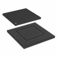
MPC8308VMAGD Freescale Semiconductor, MPC8308VMAGD Datasheet - Page 36

MPC8308VMAGD
Manufacturer Part Number
MPC8308VMAGD
Description
MPU POWERQUICC II PRO 473MAPBGA
Manufacturer
Freescale Semiconductor
Datasheets
1.MPC8308VMAGD.pdf
(90 pages)
2.MPC8308VMAGD.pdf
(2 pages)
3.MPC8308VMAGD.pdf
(1170 pages)
4.MPC8308VMAGD.pdf
(14 pages)
Specifications of MPC8308VMAGD
Processor Type
MPC83xx PowerQUICC II Pro 32-Bit
Speed
400MHz
Voltage
1V
Mounting Type
Surface Mount
Package / Case
473-MAPBGA
Product
Network Processor
Data Rate
256 bps
Frequency
400 MHz
Supply Voltage (max)
3.6 V
Supply Voltage (min)
3 V
Supply Current (max)
5 uA
Maximum Operating Temperature
+ 105 C
Minimum Operating Temperature
0 C
Interface
I2C, JTAG, SPI
Mounting Style
SMD/SMT
Lead Free Status / RoHS Status
Lead free / RoHS Compliant
Features
-
Lead Free Status / Rohs Status
Lead free / RoHS Compliant
Available stocks
Company
Part Number
Manufacturer
Quantity
Price
Company:
Part Number:
MPC8308VMAGD
Manufacturer:
FREESCAL
Quantity:
300
Company:
Part Number:
MPC8308VMAGD
Manufacturer:
Freescale Semiconductor
Quantity:
10 000
Part Number:
MPC8308VMAGD
Manufacturer:
FREESCALE
Quantity:
20 000
Company:
Part Number:
MPC8308VMAGD400/266
Manufacturer:
FREESCAL
Quantity:
300
Company:
Part Number:
MPC8308VMAGDA
Manufacturer:
Freescale Semiconductor
Quantity:
10 000
- MPC8308VMAGD PDF datasheet
- MPC8308VMAGD PDF datasheet #2
- MPC8308VMAGD PDF datasheet #3
- MPC8308VMAGD PDF datasheet #4
- Current page: 36 of 1170
- Download datasheet (9Mb)
Figure
Number
18-10
18-11
18-12
18-13
18-14
18-15
19-1
19-2
19-3
19-4
19-5
19-6
19-7
19-8
19-9
19-10
19-11
19-12
19-13
19-14
19-15
20-1
21-1
21-2
21-3
21-4
21-5
21-6
21-7
xxxvi
Modem Control Register (UMCR1 and UMCR2).............................................................. 18-12
Line Status Register (ULSR1 and ULSR2) ........................................................................ 18-13
Scratch Register (USCR) .................................................................................................... 18-14
Alternate Function Register (UAFR) .................................................................................. 18-14
DMA Status Register (UDSR) ............................................................................................ 18-15
UART Bus Interface Transaction Protocol Example .......................................................... 18-17
SPI Block Diagram ............................................................................................................... 19-1
Single-Master/Multi-Slave Configuration ............................................................................ 19-3
Multiple-Master Configuration ............................................................................................. 19-5
SPMODE-SPI Mode Register Definition ............................................................................. 19-8
SPI Transfer Format with SPMODE[CP] = 0..................................................................... 19-10
SPI Transfer Format with SPMODE[CP] = 1..................................................................... 19-10
SPIE—SPI Event Register Definition................................................................................. 19-11
SPIM—SPI Mask Register Definition ................................................................................ 19-12
SPI Command Register Definition ..................................................................................... 19-13
SPI Transmit Data Hold Register Definition ...................................................................... 19-13
SPI Receive Data Hold Register Definition........................................................................ 19-14
Example SPMODE[REV] = 0 SPMODE[LEN] = 7 LSB Sent First.................................. 19-14
Example SPMODE[REV] = 1 SPMODE[LEN] = 7 MSB Sent First................................. 19-14
Example SPMODE[REV] = 1 SPMODE[LEN] = 15 MSB Sent First............................... 19-14
Example SPMODE[REV] = 0 SPMODE[LEN] = 15 LSB Sent First................................ 19-15
JTAG Interface Block Diagram ............................................................................................ 20-1
GPIO Module Block Diagram .............................................................................................. 21-1
GPIO Direction Register (GPDIR) ....................................................................................... 21-3
GPIO Open Drain Register (GPODR) .................................................................................. 21-3
GPIO Data Register (GPDAT) .............................................................................................. 21-4
GPIO Interrupt Event Register (GPIER) .............................................................................. 21-4
GPIO Interrupt Mask Register (GPIMR).............................................................................. 21-5
GPIO Interrupt Control Register (GPICR) ........................................................................... 21-5
MPC8308 PowerQUICC II Pro Processor Reference Manual, Rev. 0
Figures
Title
Freescale Semiconductor
Number
Page
Related parts for MPC8308VMAGD
Image
Part Number
Description
Manufacturer
Datasheet
Request
R
Part Number:
Description:
Development Boards & Kits - Other Processors MPC8308-NSG
Manufacturer:
Freescale Semiconductor
Datasheet:

Part Number:
Description:
MCU, MPU & DSP Development Tools For MPC8308 Ethernet USB I2C SPI
Manufacturer:
Freescale Semiconductor
Datasheet:

Part Number:
Description:
MCU, MPU & DSP Development Tools For MPC8308 Ethernet USB 32bit
Manufacturer:
Freescale Semiconductor
Datasheet:
Part Number:
Description:
Mpc8308 Powerquicc Ii Pro Processor Hardware Specification
Manufacturer:
Freescale Semiconductor, Inc
Datasheet:

Part Number:
Description:
BOARD REF DESIGN MPC8308
Manufacturer:
Freescale Semiconductor
Datasheet:

Part Number:
Description:
MPC8308 PowerQUICC II Pro Processor Hardware Specification
Manufacturer:
FREESCALE [Freescale Semiconductor, Inc]
Datasheet:
Part Number:
Description:
Microprocessors - MPU E300 ext tmp Qual266
Manufacturer:
Freescale Semiconductor
Datasheet:
Part Number:
Description:
Microprocessors - MPU E300 ext tmp Qual333
Manufacturer:
Freescale Semiconductor
Datasheet:
Part Number:
Description:
Microprocessors - MPU E300 EXT TEMP PB 400
Manufacturer:
Freescale Semiconductor
Datasheet:
Part Number:
Description:
Microprocessors - MPU E300 MP Pb 266
Manufacturer:
Freescale Semiconductor
Datasheet:
Part Number:
Description:
Microprocessors - MPU E300 MP Pb 400
Manufacturer:
Freescale Semiconductor
Datasheet:
Part Number:
Description:
Microprocessors - MPU E300 MP Pb 333
Manufacturer:
Freescale Semiconductor
Datasheet:
Part Number:
Description:
Manufacturer:
Freescale Semiconductor, Inc
Datasheet:
Part Number:
Description:
Manufacturer:
Freescale Semiconductor, Inc
Datasheet:
Part Number:
Description:
Manufacturer:
Freescale Semiconductor, Inc
Datasheet:


