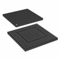
MPC8308VMAGD Freescale Semiconductor, MPC8308VMAGD Datasheet - Page 117

MPC8308VMAGD
Manufacturer Part Number
MPC8308VMAGD
Description
MPU POWERQUICC II PRO 473MAPBGA
Manufacturer
Freescale Semiconductor
Datasheets
1.MPC8308VMAGD.pdf
(90 pages)
2.MPC8308VMAGD.pdf
(2 pages)
3.MPC8308VMAGD.pdf
(1170 pages)
4.MPC8308VMAGD.pdf
(14 pages)
Specifications of MPC8308VMAGD
Processor Type
MPC83xx PowerQUICC II Pro 32-Bit
Speed
400MHz
Voltage
1V
Mounting Type
Surface Mount
Package / Case
473-MAPBGA
Product
Network Processor
Data Rate
256 bps
Frequency
400 MHz
Supply Voltage (max)
3.6 V
Supply Voltage (min)
3 V
Supply Current (max)
5 uA
Maximum Operating Temperature
+ 105 C
Minimum Operating Temperature
0 C
Interface
I2C, JTAG, SPI
Mounting Style
SMD/SMT
Lead Free Status / RoHS Status
Lead free / RoHS Compliant
Features
-
Lead Free Status / Rohs Status
Lead free / RoHS Compliant
Available stocks
Company
Part Number
Manufacturer
Quantity
Price
Company:
Part Number:
MPC8308VMAGD
Manufacturer:
FREESCAL
Quantity:
300
Company:
Part Number:
MPC8308VMAGD
Manufacturer:
Freescale Semiconductor
Quantity:
10 000
Part Number:
MPC8308VMAGD
Manufacturer:
FREESCALE
Quantity:
20 000
Company:
Part Number:
MPC8308VMAGD400/266
Manufacturer:
FREESCAL
Quantity:
300
Company:
Part Number:
MPC8308VMAGDA
Manufacturer:
Freescale Semiconductor
Quantity:
10 000
- MPC8308VMAGD PDF datasheet
- MPC8308VMAGD PDF datasheet #2
- MPC8308VMAGD PDF datasheet #3
- MPC8308VMAGD PDF datasheet #4
- Current page: 117 of 1170
- Download datasheet (9Mb)
4.3.1.2
The example described in
input signal (CFG_RESET_SOURCE). The reset sequence duration is measured from the negation of
PORESET to the negation of HRESET. Note that the duration mentioned in
not represent cases in which the process of loading the reset configuration word had to be retried due to
errors.
4.3.2
The reset configuration words control the clock ratios and other basic device functions, such as, boot
location, eTSEC mode, and endian mode. The reset configuration words are loaded from NOR Flash,
NAND Flash, or the I
Section 4.3.1, “Reset Configuration Signals,”
Although the configuration reset words are loaded during hard reset flows, the clocks and PLL modes are
reset only when PORESET is asserted during a power-on reset flow. See
The values of fields in the reset configuration words registers (RCWLR and RCWHR) reflect only their
state during the reset flow. Some of these parameters and modes can be modified by changing their values
in the memory-mapped registers of other units, which does not affect RCWLR and RCWHR.
The reset configuration settings are accessible to software through the following read-only
memory-mapped registers:
See
Freescale Semiconductor
•
•
•
•
Section 4.5, “Memory Map/Register Definitions.”
Configuration
Reset configuration word low register (RCWLR)
Reset configuration word high register (RCWHR)
Reset status register (RSR)
System PLL mode register (SPMR)
I
2
C EEPROM
Words
Reset Configuration Words
Yes
No
Selecting Reset Configuration Input Signals
SYS_CLK_IN
2
Frequency
C interfaces or from hard-coded values during the power-on or hard reset flows. See
MPC8308 PowerQUICC II Pro Processor Reference Manual, Rev. 0
33 MHz
33 MHz
Table 4-6
Table 4-6. Selecting Reset Configuration Input Signals
0000
(RCW loaded from NOR Flash)
0100 (I
shows how the user should pull down or pull up the reset configuration
CFG_RESET_SOURCE[0:3]
2
C EEPROM)
for information on the reset configuration word source.
SYS_CLK_IN Cycles
Reset Sequence
Duration in
Section 4.2.1.2, “Reset Actions.”
106534
15210
Table 4-6
Reset, Clocking, and Initialization
is typical, and does
Duration
456
196
μ
μ
s
s
4-9
Related parts for MPC8308VMAGD
Image
Part Number
Description
Manufacturer
Datasheet
Request
R
Part Number:
Description:
Development Boards & Kits - Other Processors MPC8308-NSG
Manufacturer:
Freescale Semiconductor
Datasheet:

Part Number:
Description:
MCU, MPU & DSP Development Tools For MPC8308 Ethernet USB I2C SPI
Manufacturer:
Freescale Semiconductor
Datasheet:

Part Number:
Description:
MCU, MPU & DSP Development Tools For MPC8308 Ethernet USB 32bit
Manufacturer:
Freescale Semiconductor
Datasheet:
Part Number:
Description:
Mpc8308 Powerquicc Ii Pro Processor Hardware Specification
Manufacturer:
Freescale Semiconductor, Inc
Datasheet:

Part Number:
Description:
BOARD REF DESIGN MPC8308
Manufacturer:
Freescale Semiconductor
Datasheet:

Part Number:
Description:
MPC8308 PowerQUICC II Pro Processor Hardware Specification
Manufacturer:
FREESCALE [Freescale Semiconductor, Inc]
Datasheet:
Part Number:
Description:
Microprocessors - MPU E300 ext tmp Qual266
Manufacturer:
Freescale Semiconductor
Datasheet:
Part Number:
Description:
Microprocessors - MPU E300 ext tmp Qual333
Manufacturer:
Freescale Semiconductor
Datasheet:
Part Number:
Description:
Microprocessors - MPU E300 EXT TEMP PB 400
Manufacturer:
Freescale Semiconductor
Datasheet:
Part Number:
Description:
Microprocessors - MPU E300 MP Pb 266
Manufacturer:
Freescale Semiconductor
Datasheet:
Part Number:
Description:
Microprocessors - MPU E300 MP Pb 400
Manufacturer:
Freescale Semiconductor
Datasheet:
Part Number:
Description:
Microprocessors - MPU E300 MP Pb 333
Manufacturer:
Freescale Semiconductor
Datasheet:
Part Number:
Description:
Manufacturer:
Freescale Semiconductor, Inc
Datasheet:
Part Number:
Description:
Manufacturer:
Freescale Semiconductor, Inc
Datasheet:
Part Number:
Description:
Manufacturer:
Freescale Semiconductor, Inc
Datasheet:


