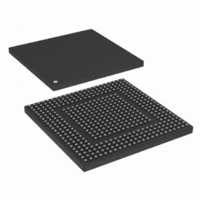
MPC8308VMAGD Freescale Semiconductor, MPC8308VMAGD Datasheet - Page 25

MPC8308VMAGD
Manufacturer Part Number
MPC8308VMAGD
Description
MPU POWERQUICC II PRO 473MAPBGA
Manufacturer
Freescale Semiconductor
Datasheets
1.MPC8308VMAGD.pdf
(90 pages)
2.MPC8308VMAGD.pdf
(2 pages)
3.MPC8308VMAGD.pdf
(1170 pages)
4.MPC8308VMAGD.pdf
(14 pages)
Specifications of MPC8308VMAGD
Processor Type
MPC83xx PowerQUICC II Pro 32-Bit
Speed
400MHz
Voltage
1V
Mounting Type
Surface Mount
Package / Case
473-MAPBGA
Product
Network Processor
Data Rate
256 bps
Frequency
400 MHz
Supply Voltage (max)
3.6 V
Supply Voltage (min)
3 V
Supply Current (max)
5 uA
Maximum Operating Temperature
+ 105 C
Minimum Operating Temperature
0 C
Interface
I2C, JTAG, SPI
Mounting Style
SMD/SMT
Lead Free Status / RoHS Status
Lead free / RoHS Compliant
Features
-
Lead Free Status / Rohs Status
Lead free / RoHS Compliant
Available stocks
Company
Part Number
Manufacturer
Quantity
Price
Company:
Part Number:
MPC8308VMAGD
Manufacturer:
FREESCAL
Quantity:
300
Company:
Part Number:
MPC8308VMAGD
Manufacturer:
Freescale Semiconductor
Quantity:
10 000
Part Number:
MPC8308VMAGD
Manufacturer:
FREESCALE
Quantity:
20 000
Company:
Part Number:
MPC8308VMAGD400/266
Manufacturer:
FREESCAL
Quantity:
300
Company:
Part Number:
MPC8308VMAGDA
Manufacturer:
Freescale Semiconductor
Quantity:
10 000
- MPC8308VMAGD PDF datasheet
- MPC8308VMAGD PDF datasheet #2
- MPC8308VMAGD PDF datasheet #3
- MPC8308VMAGD PDF datasheet #4
- Current page: 25 of 1170
- Download datasheet (9Mb)
Figure
Number
10-65
10-66
10-67
10-68
10-69
10-70
10-71
10-72
10-73
10-74
10-75
10-76
10-77
11-1
11-2
11-3
11-4
11-5
11-6
11-7
11-8
11-9
11-10
11-11
11-12
11-13
11-14
11-15
11-16
11-17
11-18
11-19
11-20
11-21
11-22
11-23
11-24
11-25
11-26
11-27
12-1
Freescale Semiconductor
LCSn Signal Selection ........................................................................................................ 10-78
LBS Signal Selection .......................................................................................................... 10-78
UPM Read Access Data Sampling...................................................................................... 10-80
Effect of LUPWAIT Signal ................................................................................................. 10-81
GPCM Address Timings ..................................................................................................... 10-82
GPCM Data Timings........................................................................................................... 10-83
Interface to Different Port-Size Devices ............................................................................. 10-83
Single-Beat Read Access to FPM DRAM .......................................................................... 10-89
Single-Beat Write Access to FPM DRAM ......................................................................... 10-91
Burst Read Access to FPM DRAM Using LOOP (Two Beats).......................................... 10-93
Refresh Cycle (CBR) to FPM DRAM ................................................................................ 10-95
Exception Cycle .................................................................................................................. 10-96
Interface to ZBT SRAM ..................................................................................................... 10-98
System Connection of the eSDHC........................................................................................ 11-1
eSDHC Block Diagram......................................................................................................... 11-2
DMA System Address Register (DSADDR) ........................................................................ 11-6
Block Attributes Register (BLKATTR) ................................................................................ 11-6
Command Argument Register (CMDARG) ......................................................................... 11-7
Transfer Type Register (XFERTYP)..................................................................................... 11-8
Command Response 0–3 Register (CMDRSPn) .................................................................11-11
Buffer Data Port Register (DATPORT) .............................................................................. 11-13
Present State Register (PRSSTAT)...................................................................................... 11-13
Protocol Control Register (PROCTL)................................................................................. 11-17
System Control Register (SYSCTL)................................................................................... 11-20
Interrupt Status Register (IRQSTAT) .................................................................................. 11-24
Interrupt Status Enable Register (IRQSTATEN) ................................................................ 11-28
Interrupt Signal Enable Register (IRQSIGEN)................................................................... 11-30
Auto CMD12 Error Status Register (AUTOC12ERR) ....................................................... 11-32
Host Capabilities Register (HOSTCAPBLT)...................................................................... 11-34
Watermark Level Register (WML) ..................................................................................... 11-35
Force Event Register (FEVT) ............................................................................................. 11-36
Host Controller Version Register (HOSTVER) .................................................................. 11-37
eSDHC Buffer Scheme ....................................................................................................... 11-38
Example of Dividing a Large Data Transfer ....................................................................... 11-40
DMA CSB Interface Block ................................................................................................. 11-41
Command CRC Shift Register ............................................................................................ 11-42
Two Stages of Clock Divider .............................................................................................. 11-43
a) Card Interrupt Scheme; b) Card Interrupt Detection and Handling Procedure .............. 11-45
Flow Diagram for Card Detection ...................................................................................... 11-47
Flow Chart for Reset of eSDHC and SD I/O Card ............................................................. 11-48
DMA Block Diagram............................................................................................................ 12-1
MPC8308 PowerQUICC II Pro Processor Reference Manual, Rev. 0
Figures
Title
Number
Page
xxv
Related parts for MPC8308VMAGD
Image
Part Number
Description
Manufacturer
Datasheet
Request
R
Part Number:
Description:
Development Boards & Kits - Other Processors MPC8308-NSG
Manufacturer:
Freescale Semiconductor
Datasheet:

Part Number:
Description:
MCU, MPU & DSP Development Tools For MPC8308 Ethernet USB I2C SPI
Manufacturer:
Freescale Semiconductor
Datasheet:

Part Number:
Description:
MCU, MPU & DSP Development Tools For MPC8308 Ethernet USB 32bit
Manufacturer:
Freescale Semiconductor
Datasheet:
Part Number:
Description:
Mpc8308 Powerquicc Ii Pro Processor Hardware Specification
Manufacturer:
Freescale Semiconductor, Inc
Datasheet:

Part Number:
Description:
BOARD REF DESIGN MPC8308
Manufacturer:
Freescale Semiconductor
Datasheet:

Part Number:
Description:
MPC8308 PowerQUICC II Pro Processor Hardware Specification
Manufacturer:
FREESCALE [Freescale Semiconductor, Inc]
Datasheet:
Part Number:
Description:
Microprocessors - MPU E300 ext tmp Qual266
Manufacturer:
Freescale Semiconductor
Datasheet:
Part Number:
Description:
Microprocessors - MPU E300 ext tmp Qual333
Manufacturer:
Freescale Semiconductor
Datasheet:
Part Number:
Description:
Microprocessors - MPU E300 EXT TEMP PB 400
Manufacturer:
Freescale Semiconductor
Datasheet:
Part Number:
Description:
Microprocessors - MPU E300 MP Pb 266
Manufacturer:
Freescale Semiconductor
Datasheet:
Part Number:
Description:
Microprocessors - MPU E300 MP Pb 400
Manufacturer:
Freescale Semiconductor
Datasheet:
Part Number:
Description:
Microprocessors - MPU E300 MP Pb 333
Manufacturer:
Freescale Semiconductor
Datasheet:
Part Number:
Description:
Manufacturer:
Freescale Semiconductor, Inc
Datasheet:
Part Number:
Description:
Manufacturer:
Freescale Semiconductor, Inc
Datasheet:
Part Number:
Description:
Manufacturer:
Freescale Semiconductor, Inc
Datasheet:


