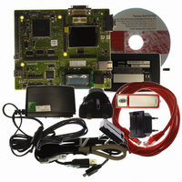
R0K572030S000BE Renesas Electronics America, R0K572030S000BE Datasheet - Page 987

R0K572030S000BE
Manufacturer Part Number
R0K572030S000BE
Description
KIT DEV FOR SH7203
Manufacturer
Renesas Electronics America
Series
Renesas Starter Kits (RSK)r
Type
MCUr
Specifications of R0K572030S000BE
Contents
CPU Board, LCD Module, E10A-Lite Emulator, Cable, QuickStart Guide and CD-ROM
Silicon Manufacturer
Renesas
Kit Contents
Board
Silicon Family Name
SH7203
Silicon Core Number
R5S72030W200FP
Tool / Board Applications
General Purpose MCU, MPU, DSP, DSC
Mcu Supported Families
SH7203
Lead Free Status / RoHS Status
Contains lead / RoHS non-compliant
For Use With/related Products
SH7203
Lead Free Status / Rohs Status
Compliant
- Current page: 987 of 1686
- Download datasheet (10Mb)
Bit 7 - Overload Frame (IRR7): Flag indicating that the RCAN-TL1 has detected a condition
that should initiate the transmission of an overload frame. Note that in the condition of
transmission being prevented, such as listen only mode, an Overload Frame will NOT be
transmitted, but IRR7 will still be set. IRR7 remains asserted until reset by writing a ‘1’ to this bit
position - writing a ‘0’ has no effect.
Bit 6 - Bus Off Interrupt Flag (IRR6): This bit is set when RCAN-TL1 enters the Bus-off state
or when RCAN-TL1 leaves Bus-off and returns to Error-Active. The cause therefore is the
existing condition TEC ≥ 256 at the node or the end of the Bus-off recovery sequence (128X11
consecutive recessive bits) or the transition from Bus Off to Halt (automatic or manual). This bit
remains set even if the RCAN-TL1 node leaves the bus-off condition, and needs to be explicitly
cleared by S/W. The S/W is expected to read the GSR0 to judge whether RCAN-TL1 is in the bus-
off or error active status. It is cleared by writing a ‘1’ to this bit position even if the node is still
bus-off. Writing a ‘0’ has no effect.
Bit 5 - Error Passive Interrupt Flag (IRR5): Interrupt flag indicating the error passive state
caused by the transmit or receive error counter or by Error Passive forced by test mode. This bit is
reset by writing a ‘1’ to this bit position, writing a ‘0’ has no effect. If this bit is cleared the node
may still be error passive. Please note that the SW needs to check GSR0 and GSR5 to judge
whether RCAN-TL1 is in Error Passive or Bus Off status.
Bit 7: IRR7
0
1
Bit 6: IRR6
0
1
Bit 5: IRR5
0
1
Description
[Clearing condition] Writing 1 (Initial value)
[Setting conditions] Overload condition detected
Description
[Clearing condition] Writing 1 (Initial value)
Enter Bus off state caused by transmit error or Error Active state returning
from Bus-off
[Setting condition]
When TEC becomes ≥ 256 or End of Bus-off after 128X11 consecutive
recessive bits or transition from Bus Off to Halt
Description
[Clearing condition] Writing 1 (Initial value)
Error passive state caused by transmit/receive error
[Setting condition]
When TEC ≥ 128 or REC ≥ 128 or Error Passive test mode is used
Section 19 Controller Area Network (RCAN-TL1)
Rev. 3.00 Sep. 28, 2009 Page 955 of 1650
REJ09B0313-0300
Related parts for R0K572030S000BE
Image
Part Number
Description
Manufacturer
Datasheet
Request
R

Part Number:
Description:
KIT STARTER FOR M16C/29
Manufacturer:
Renesas Electronics America
Datasheet:

Part Number:
Description:
KIT STARTER FOR R8C/2D
Manufacturer:
Renesas Electronics America
Datasheet:

Part Number:
Description:
R0K33062P STARTER KIT
Manufacturer:
Renesas Electronics America
Datasheet:

Part Number:
Description:
KIT STARTER FOR R8C/23 E8A
Manufacturer:
Renesas Electronics America
Datasheet:

Part Number:
Description:
KIT STARTER FOR R8C/25
Manufacturer:
Renesas Electronics America
Datasheet:

Part Number:
Description:
KIT STARTER H8S2456 SHARPE DSPLY
Manufacturer:
Renesas Electronics America
Datasheet:

Part Number:
Description:
KIT STARTER FOR R8C38C
Manufacturer:
Renesas Electronics America
Datasheet:

Part Number:
Description:
KIT STARTER FOR R8C35C
Manufacturer:
Renesas Electronics America
Datasheet:

Part Number:
Description:
KIT STARTER FOR R8CL3AC+LCD APPS
Manufacturer:
Renesas Electronics America
Datasheet:

Part Number:
Description:
KIT STARTER FOR RX610
Manufacturer:
Renesas Electronics America
Datasheet:

Part Number:
Description:
KIT STARTER FOR R32C/118
Manufacturer:
Renesas Electronics America
Datasheet:

Part Number:
Description:
KIT DEV RSK-R8C/26-29
Manufacturer:
Renesas Electronics America
Datasheet:

Part Number:
Description:
KIT STARTER FOR SH7124
Manufacturer:
Renesas Electronics America
Datasheet:

Part Number:
Description:
KIT STARTER FOR H8SX/1622
Manufacturer:
Renesas Electronics America
Datasheet:

Part Number:
Description:
KIT STARTER FOR R8C/18191A1B
Manufacturer:
Renesas Electronics America
Datasheet:


