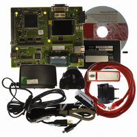
R0K572030S000BE Renesas Electronics America, R0K572030S000BE Datasheet - Page 229

R0K572030S000BE
Manufacturer Part Number
R0K572030S000BE
Description
KIT DEV FOR SH7203
Manufacturer
Renesas Electronics America
Series
Renesas Starter Kits (RSK)r
Type
MCUr
Specifications of R0K572030S000BE
Contents
CPU Board, LCD Module, E10A-Lite Emulator, Cable, QuickStart Guide and CD-ROM
Silicon Manufacturer
Renesas
Kit Contents
Board
Silicon Family Name
SH7203
Silicon Core Number
R5S72030W200FP
Tool / Board Applications
General Purpose MCU, MPU, DSP, DSC
Mcu Supported Families
SH7203
Lead Free Status / RoHS Status
Contains lead / RoHS non-compliant
For Use With/related Products
SH7203
Lead Free Status / Rohs Status
Compliant
- Current page: 229 of 1686
- Download datasheet (10Mb)
The user break controller (UBC) provides functions that simplify program debugging. These
functions make it easy to design an effective self-monitoring debugger, enabling the chip to debug
programs without using an in-circuit emulator. Instruction fetch or data read/write (bus cycle
(CPU or DMAC) selection in the case of data read/write), data size, data contents, address value,
and stop timing in the case of instruction fetch are break conditions that can be set in the UBC.
Since this LSI uses a Harvard architecture, instruction fetch on the CPU bus (C bus) is performed
by issuing bus cycles on the instruction fetch bus (F bus), and data access on the C bus is
performed by issuing bus cycles on the memory access bus (M bus). The internal bus (I bus)
consists of the internal CPU bus, on which the CPU issues bus cycles, and the internal DMA bus,
on which the DMA issues bus cycles. The UBC monitors the C bus and I bus.
7.1
1. The following break comparison conditions can be set.
2. In an instruction fetch cycle, it can be selected whether the start of user break interrupt
3. When a break condition is satisfied, a trigger signal is output from the UBCTRG pin.
Number of break channels: two channels (channels 0 and 1)
User break can be requested as the independent condition on channels 0 and 1.
⎯ Address
⎯ Data
⎯ Bus selection when I bus is selected
⎯ Bus cycle
⎯ Read/write
⎯ Operand size
exception processing is set before or after an instruction is executed.
Comparison of the 32-bit address is maskable in 1-bit units.
One of the four address buses (F address bus (FAB), M address bus (MAB), internal CPU
address bus (ICAB), and internal DMA address bus (IDAB)) can be selected.
Comparison of the 32-bit data is maskable in 1-bit units.
One of the three data buses (M data bus (MDB), internal CPU data bus (ICDB), and
internal DMA data bus (IDDB)) can be selected.
Internal CPU bus or internal DMA bus
Instruction fetch (only when C bus is selected) or data access
Byte, word, and longword
Features
Section 7 User Break Controller (UBC)
Rev. 3.00 Sep. 28, 2009 Page 197 of 1650
Section 7 User Break Controller (UBC)
REJ09B0313-0300
Related parts for R0K572030S000BE
Image
Part Number
Description
Manufacturer
Datasheet
Request
R

Part Number:
Description:
KIT STARTER FOR M16C/29
Manufacturer:
Renesas Electronics America
Datasheet:

Part Number:
Description:
KIT STARTER FOR R8C/2D
Manufacturer:
Renesas Electronics America
Datasheet:

Part Number:
Description:
R0K33062P STARTER KIT
Manufacturer:
Renesas Electronics America
Datasheet:

Part Number:
Description:
KIT STARTER FOR R8C/23 E8A
Manufacturer:
Renesas Electronics America
Datasheet:

Part Number:
Description:
KIT STARTER FOR R8C/25
Manufacturer:
Renesas Electronics America
Datasheet:

Part Number:
Description:
KIT STARTER H8S2456 SHARPE DSPLY
Manufacturer:
Renesas Electronics America
Datasheet:

Part Number:
Description:
KIT STARTER FOR R8C38C
Manufacturer:
Renesas Electronics America
Datasheet:

Part Number:
Description:
KIT STARTER FOR R8C35C
Manufacturer:
Renesas Electronics America
Datasheet:

Part Number:
Description:
KIT STARTER FOR R8CL3AC+LCD APPS
Manufacturer:
Renesas Electronics America
Datasheet:

Part Number:
Description:
KIT STARTER FOR RX610
Manufacturer:
Renesas Electronics America
Datasheet:

Part Number:
Description:
KIT STARTER FOR R32C/118
Manufacturer:
Renesas Electronics America
Datasheet:

Part Number:
Description:
KIT DEV RSK-R8C/26-29
Manufacturer:
Renesas Electronics America
Datasheet:

Part Number:
Description:
KIT STARTER FOR SH7124
Manufacturer:
Renesas Electronics America
Datasheet:

Part Number:
Description:
KIT STARTER FOR H8SX/1622
Manufacturer:
Renesas Electronics America
Datasheet:

Part Number:
Description:
KIT STARTER FOR R8C/18191A1B
Manufacturer:
Renesas Electronics America
Datasheet:


