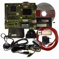
R0K572030S000BE Renesas Electronics America, R0K572030S000BE Datasheet - Page 1247

R0K572030S000BE
Manufacturer Part Number
R0K572030S000BE
Description
KIT DEV FOR SH7203
Manufacturer
Renesas Electronics America
Series
Renesas Starter Kits (RSK)r
Type
MCUr
Specifications of R0K572030S000BE
Contents
CPU Board, LCD Module, E10A-Lite Emulator, Cable, QuickStart Guide and CD-ROM
Silicon Manufacturer
Renesas
Kit Contents
Board
Silicon Family Name
SH7203
Silicon Core Number
R5S72030W200FP
Tool / Board Applications
General Purpose MCU, MPU, DSP, DSC
Mcu Supported Families
SH7203
Lead Free Status / RoHS Status
Contains lead / RoHS non-compliant
For Use With/related Products
SH7203
Lead Free Status / Rohs Status
Compliant
- Current page: 1247 of 1686
- Download datasheet (10Mb)
Also, this module automatically judges the direction bit (bit 8 of the bmRequestType) and the
request data length (wLength) of the USB request that was received, and then distinguishes
between control read transfers, control write transfers, and no-data control transfers, and controls
the stage transition. For a wrong sequence, the sequence error of the control transfer stage
transition interrupt is generated, and the software is notified. For information on the stage control
of this module, see figure 23.18.
(b)
Data transfers corresponding to USB requests that have been received should be done using the
DCP. Before accessing the DCP buffer memory, the access direction should be specified using the
ISEL bit in CFIFOSEL.
If the data being transferred is larger than the size of the DCP buffer memory, the data transfer
should be carried out using the BRDY interrupt for control write transfers and the BEMP interrupt
for control read transfers.
With control write transfers during high-speed operation, the NYET handshake response is carried
out based on the state of the buffer memory. For information on the NYET handshake, see section
23.4.6 (2), NYET Handshake Control when the Function Controller Function is Selected.
(c)
Control transfers are terminated by setting the CCPL bit to 1 with the PID bit in DCPCTR set to
PID = BUF.
After the above settings have been entered, this module automatically executes the status stage in
accordance with the data transfer direction determined at the setup stage. The specific procedure is
as follows.
1. For control read transfers:
2. For control write transfers and no-data control transfers:
The zero-length packet is received from the USB host, and this module sends an ACK
response.
This module sends a zero-length packet and receives an ACK response from the USB host.
Data Stage
Status Stage
Section 23 USB 2.0 Host/Function Module (USB)
Rev. 3.00 Sep. 28, 2009 Page 1215 of 1650
REJ09B0313-0300
Related parts for R0K572030S000BE
Image
Part Number
Description
Manufacturer
Datasheet
Request
R

Part Number:
Description:
KIT STARTER FOR M16C/29
Manufacturer:
Renesas Electronics America
Datasheet:

Part Number:
Description:
KIT STARTER FOR R8C/2D
Manufacturer:
Renesas Electronics America
Datasheet:

Part Number:
Description:
R0K33062P STARTER KIT
Manufacturer:
Renesas Electronics America
Datasheet:

Part Number:
Description:
KIT STARTER FOR R8C/23 E8A
Manufacturer:
Renesas Electronics America
Datasheet:

Part Number:
Description:
KIT STARTER FOR R8C/25
Manufacturer:
Renesas Electronics America
Datasheet:

Part Number:
Description:
KIT STARTER H8S2456 SHARPE DSPLY
Manufacturer:
Renesas Electronics America
Datasheet:

Part Number:
Description:
KIT STARTER FOR R8C38C
Manufacturer:
Renesas Electronics America
Datasheet:

Part Number:
Description:
KIT STARTER FOR R8C35C
Manufacturer:
Renesas Electronics America
Datasheet:

Part Number:
Description:
KIT STARTER FOR R8CL3AC+LCD APPS
Manufacturer:
Renesas Electronics America
Datasheet:

Part Number:
Description:
KIT STARTER FOR RX610
Manufacturer:
Renesas Electronics America
Datasheet:

Part Number:
Description:
KIT STARTER FOR R32C/118
Manufacturer:
Renesas Electronics America
Datasheet:

Part Number:
Description:
KIT DEV RSK-R8C/26-29
Manufacturer:
Renesas Electronics America
Datasheet:

Part Number:
Description:
KIT STARTER FOR SH7124
Manufacturer:
Renesas Electronics America
Datasheet:

Part Number:
Description:
KIT STARTER FOR H8SX/1622
Manufacturer:
Renesas Electronics America
Datasheet:

Part Number:
Description:
KIT STARTER FOR R8C/18191A1B
Manufacturer:
Renesas Electronics America
Datasheet:


