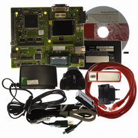
R0K572030S000BE Renesas Electronics America, R0K572030S000BE Datasheet - Page 1667

R0K572030S000BE
Manufacturer Part Number
R0K572030S000BE
Description
KIT DEV FOR SH7203
Manufacturer
Renesas Electronics America
Series
Renesas Starter Kits (RSK)r
Type
MCUr
Specifications of R0K572030S000BE
Contents
CPU Board, LCD Module, E10A-Lite Emulator, Cable, QuickStart Guide and CD-ROM
Silicon Manufacturer
Renesas
Kit Contents
Board
Silicon Family Name
SH7203
Silicon Core Number
R5S72030W200FP
Tool / Board Applications
General Purpose MCU, MPU, DSP, DSC
Mcu Supported Families
SH7203
Lead Free Status / RoHS Status
Contains lead / RoHS non-compliant
For Use With/related Products
SH7203
Lead Free Status / Rohs Status
Compliant
- Current page: 1667 of 1686
- Download datasheet (10Mb)
Item
28.3.4 Deep Standby
Mode
(3) Operation after
Canceling Deep Standby
Mode
28.4.3 Notice about
Power-On Reset
Exception Handling
30.2 Register Bits
Page
1433
1435
1496
1498
Revision (See Manual for Details)
Description amended
… Pins retain the state immediately before the transition to
deep standby mode. However, in system activation through
the external bus, the retention of the states of the external
bus control pins is cancelled so that programs can be fetched
after cancellation of deep standby mode. Other pins, after
cancellation of deep standby mode, continue to retain the pin
states until writing 0 to the IOKEEP bit in DSFR
same bit. In system activation from the on-chip RAM (for data
retention), after cancellation of deep standby mode, both the
external bus control pins and other pins continues to retain
the pin states until writing 0 to the IOKEEP bit in DSFR
from the same bit.
Description amended
•
Table amended
Table amended
Module
Name
RCAN-TL1
Module
Name
RCAN-TL1
After (1) power-on reset by RES pin is released, (2) the
LSI transit to deep standby mode, and (3) the deep
standby mode is cancelled, if there is a possibility that
power-on reset by WDT or H-UDI reset is occurred before
power-on reset by RES pin is executed again, the
settings of WDT or H-UDI should be done in the condition
that bit 15 (IOKEEP) and bits 9~0 of deep standby cancel
source flag register (DSFR) are all cleared after canceling
deep standby mode (if some bits are 1, please write
these as “0”
Register
Abbreviation
MCR_0
GSR_0
BCR1_0
Register
Abbreviation
CMAX_TEW_0
RFTROFF_0
RFTROFF[7] RFTROFF[6]
Bit
31/23/15/7
Bit
31/23/15/7
TS G1[3]
MCR15
MCR7
—
—
—
—
—
—
).
Bit
30/22/14/6
Bit
30/22/14/6
TS G1[2]
MCR14
MCR6
Rev. 3.00 Sep. 28, 2009 Page 1635 of 1650
—
—
—
—
—
—
RFTROFF[5] RFTROFF[4]
Bit
29/21/13/5
Bit
29/21/13/5
TS G1[1]
SJW[1]
MCR5
GSR5
—
—
—
—
—
Bit
28/20/12/4
Bit
28/20/12/4
TS G1[0]
SJW[0]
GSR4
—
—
—
—
—
—
RFTROFF[3]
Bit
27/19/11/3
Bit
27/19/11/3
TEW[3]
GSR3
—
—
—
—
—
—
—
RFTROFF[2]
Bit
26/18/10/2
Bit
26/18/10/2
TS G2[2]
CMAX[2]
TEW[2]
TST[2]
MCR2
GSR2
REJ09B0313-0300
—
—
—
Bit
25/17/9/1
Bit
25/17/9/1
RFTROFF[1] RFTROFF[0]
TS G2[1]
CMAX[1]
TEW[1]
from the
TST[1]
MCR1
GSR1
—
—
—
Bit
24/16/8/0
Bit
24/16/8/0
TS G2[0]
CMAX[0]
TEW[0]
TST[0]
MCR0
GSR0
BSP
—
—
Related parts for R0K572030S000BE
Image
Part Number
Description
Manufacturer
Datasheet
Request
R

Part Number:
Description:
KIT STARTER FOR M16C/29
Manufacturer:
Renesas Electronics America
Datasheet:

Part Number:
Description:
KIT STARTER FOR R8C/2D
Manufacturer:
Renesas Electronics America
Datasheet:

Part Number:
Description:
R0K33062P STARTER KIT
Manufacturer:
Renesas Electronics America
Datasheet:

Part Number:
Description:
KIT STARTER FOR R8C/23 E8A
Manufacturer:
Renesas Electronics America
Datasheet:

Part Number:
Description:
KIT STARTER FOR R8C/25
Manufacturer:
Renesas Electronics America
Datasheet:

Part Number:
Description:
KIT STARTER H8S2456 SHARPE DSPLY
Manufacturer:
Renesas Electronics America
Datasheet:

Part Number:
Description:
KIT STARTER FOR R8C38C
Manufacturer:
Renesas Electronics America
Datasheet:

Part Number:
Description:
KIT STARTER FOR R8C35C
Manufacturer:
Renesas Electronics America
Datasheet:

Part Number:
Description:
KIT STARTER FOR R8CL3AC+LCD APPS
Manufacturer:
Renesas Electronics America
Datasheet:

Part Number:
Description:
KIT STARTER FOR RX610
Manufacturer:
Renesas Electronics America
Datasheet:

Part Number:
Description:
KIT STARTER FOR R32C/118
Manufacturer:
Renesas Electronics America
Datasheet:

Part Number:
Description:
KIT DEV RSK-R8C/26-29
Manufacturer:
Renesas Electronics America
Datasheet:

Part Number:
Description:
KIT STARTER FOR SH7124
Manufacturer:
Renesas Electronics America
Datasheet:

Part Number:
Description:
KIT STARTER FOR H8SX/1622
Manufacturer:
Renesas Electronics America
Datasheet:

Part Number:
Description:
KIT STARTER FOR R8C/18191A1B
Manufacturer:
Renesas Electronics America
Datasheet:


