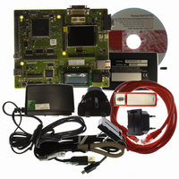
R0K572030S000BE Renesas Electronics America, R0K572030S000BE Datasheet - Page 1682

R0K572030S000BE
Manufacturer Part Number
R0K572030S000BE
Description
KIT DEV FOR SH7203
Manufacturer
Renesas Electronics America
Series
Renesas Starter Kits (RSK)r
Type
MCUr
Specifications of R0K572030S000BE
Contents
CPU Board, LCD Module, E10A-Lite Emulator, Cable, QuickStart Guide and CD-ROM
Silicon Manufacturer
Renesas
Kit Contents
Board
Silicon Family Name
SH7203
Silicon Core Number
R5S72030W200FP
Tool / Board Applications
General Purpose MCU, MPU, DSP, DSC
Mcu Supported Families
SH7203
Lead Free Status / RoHS Status
Contains lead / RoHS non-compliant
For Use With/related Products
SH7203
Lead Free Status / Rohs Status
Compliant
- Current page: 1682 of 1686
- Download datasheet (10Mb)
Setting analog input voltage ....... 1041, 1051
Setting I/O ports for RCAN-TL1.......... 1016
Setting the display resolution................ 1281
Shift instructions....................................... 81
Sign extension of word data ..................... 54
SIGN interrupt ...................................... 1190
Single address mode ............................... 434
Single mode .......................................... 1028
Single read .............................................. 336
Single write............................................. 339
Slave receive operation........................... 860
Slave transmit operation ......................... 857
Sleep mode ................................... 991, 1423
Slot illegal instructions ........................... 140
SOF interpolation function ................... 1226
Software standby mode ........................ 1424
SRAM interface with byte selection....... 362
SSI timing............................................. 1584
SSU Interrupt sources............................. 830
SSU mode............................................... 813
SSU timing ........................................... 1579
Stack after interrupt exception
handling .................................................. 181
Stack status after exception handling
ends......................................................... 144
Standby control circuit............................ 107
Status register (SR) ................................... 48
Supported DMA transfers....................... 431
Synchronous serial communication
unit (SSU)............................................... 791
System control instructions....................... 83
System matrix ......................................... 937
T
T bit .......................................................... 55
TAP controller ...................................... 1441
TDO output timing ............................... 1442
Test mode settings .................................. 988
Time slave ............................................ 1002
Rev. 3.00 Sep. 28, 2009 Page 1650 of 1650
REJ09B0313-0300
Time trigger control (TT control) ........... 933
Time triggered transmission ................... 997
Timestamp .............................................. 932
Timing to clear an interrupt source ......... 195
Transfer clock ......................................... 808
Transfer rate............................................ 839
Trap instructions ..................................... 140
TTW[1:0] (time trigger window) ............ 934
Tx-trigger control field ........................... 934
Tx-trigger time (TTT) ............................. 933
Types of exception handling and
priority order ........................................... 123
U
UBC timing........................................... 1574
Unconditional branch instructions
with no delay slot...................................... 55
USB 2.0 host/function module (USB) .. 1097
USB data bus resistor control................ 1171
USB timing ........................................... 1596
User break controller (UBC)................... 197
User break interrupt ................................ 165
User debugging interface (H-UDI) ....... 1437
Using alarm function............................... 717
Using interval timer mode ...................... 687
Using watchdog timer mode ................... 685
V
VBUS interrupt ..................................... 1189
Vector base register (VBR)....................... 49
W
Wait between access cycles .................... 380
Watchdog timer (WDT).......................... 675
WDT timing.......................................... 1577
Write-back buffer
(only for operand cache) ......................... 231
Related parts for R0K572030S000BE
Image
Part Number
Description
Manufacturer
Datasheet
Request
R

Part Number:
Description:
KIT STARTER FOR M16C/29
Manufacturer:
Renesas Electronics America
Datasheet:

Part Number:
Description:
KIT STARTER FOR R8C/2D
Manufacturer:
Renesas Electronics America
Datasheet:

Part Number:
Description:
R0K33062P STARTER KIT
Manufacturer:
Renesas Electronics America
Datasheet:

Part Number:
Description:
KIT STARTER FOR R8C/23 E8A
Manufacturer:
Renesas Electronics America
Datasheet:

Part Number:
Description:
KIT STARTER FOR R8C/25
Manufacturer:
Renesas Electronics America
Datasheet:

Part Number:
Description:
KIT STARTER H8S2456 SHARPE DSPLY
Manufacturer:
Renesas Electronics America
Datasheet:

Part Number:
Description:
KIT STARTER FOR R8C38C
Manufacturer:
Renesas Electronics America
Datasheet:

Part Number:
Description:
KIT STARTER FOR R8C35C
Manufacturer:
Renesas Electronics America
Datasheet:

Part Number:
Description:
KIT STARTER FOR R8CL3AC+LCD APPS
Manufacturer:
Renesas Electronics America
Datasheet:

Part Number:
Description:
KIT STARTER FOR RX610
Manufacturer:
Renesas Electronics America
Datasheet:

Part Number:
Description:
KIT STARTER FOR R32C/118
Manufacturer:
Renesas Electronics America
Datasheet:

Part Number:
Description:
KIT DEV RSK-R8C/26-29
Manufacturer:
Renesas Electronics America
Datasheet:

Part Number:
Description:
KIT STARTER FOR SH7124
Manufacturer:
Renesas Electronics America
Datasheet:

Part Number:
Description:
KIT STARTER FOR H8SX/1622
Manufacturer:
Renesas Electronics America
Datasheet:

Part Number:
Description:
KIT STARTER FOR R8C/18191A1B
Manufacturer:
Renesas Electronics America
Datasheet:


