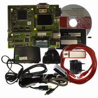
R0K572030S000BE Renesas Electronics America, R0K572030S000BE Datasheet - Page 18

R0K572030S000BE
Manufacturer Part Number
R0K572030S000BE
Description
KIT DEV FOR SH7203
Manufacturer
Renesas Electronics America
Series
Renesas Starter Kits (RSK)r
Type
MCUr
Specifications of R0K572030S000BE
Contents
CPU Board, LCD Module, E10A-Lite Emulator, Cable, QuickStart Guide and CD-ROM
Silicon Manufacturer
Renesas
Kit Contents
Board
Silicon Family Name
SH7203
Silicon Core Number
R5S72030W200FP
Tool / Board Applications
General Purpose MCU, MPU, DSP, DSC
Mcu Supported Families
SH7203
Lead Free Status / RoHS Status
Contains lead / RoHS non-compliant
For Use With/related Products
SH7203
Lead Free Status / Rohs Status
Compliant
- Current page: 18 of 1686
- Download datasheet (10Mb)
11.4 Operation ........................................................................................................................... 523
11.5 Interrupt Sources................................................................................................................ 599
11.6 Operation Timing............................................................................................................... 603
11.7 Usage Notes ....................................................................................................................... 614
Rev. 3.00 Sep. 28, 2009 Page xvi of xxx
REJ09B0313-0300
11.3.28 Timer Dead Time Enable Register (TDER)........................................................ 520
11.3.29 Timer Waveform Control Register (TWCR) ...................................................... 521
11.3.30 Bus Master Interface........................................................................................... 522
11.4.1
11.4.2
11.4.3
11.4.4
11.4.5
11.4.6
11.4.7
11.4.8
11.4.9
11.4.10 TCNT Capture at Crest and/or Trough in Complementary PWM Operation ..... 598
11.5.1
11.5.2
11.5.3
11.6.1
11.6.2
11.7.1
11.7.2
11.7.3
11.7.4
11.7.5
11.7.6
11.7.7
11.7.8
11.7.9
11.7.10 Contention between TGR Write and Input Capture............................................ 621
11.7.11 Contention between Buffer Register Write and Input Capture ........................... 622
11.7.12 TCNT2 Write and Overflow/Underflow Contention in Cascade Connection .... 622
11.7.13 Counter Value during Complementary PWM Mode Stop .................................. 624
11.7.14 Buffer Operation Setting in Complementary PWM Mode ................................. 624
11.7.15 Reset Sync PWM Mode Buffer Operation and Compare Match Flag ................ 625
11.7.16 Overflow Flags in Reset Synchronous PWM Mode ........................................... 626
11.7.17 Contention between Overflow/Underflow and Counter Clearing....................... 627
11.7.18 Contention between TCNT Write and Overflow/Underflow.............................. 628
Basic Functions................................................................................................... 523
Synchronous Operation....................................................................................... 529
Buffer Operation................................................................................................. 531
Cascaded Operation ............................................................................................ 535
PWM Modes....................................................................................................... 540
Phase Counting Mode......................................................................................... 545
Reset-Synchronized PWM Mode ....................................................................... 552
Complementary PWM Mode.............................................................................. 555
A/D Converter Start Request Delaying Function................................................ 594
Interrupt Sources and Priorities .......................................................................... 599
DMAC Activation .............................................................................................. 601
A/D Converter Activation................................................................................... 601
Input/Output Timing ........................................................................................... 603
Interrupt Signal Timing ...................................................................................... 610
Module Standby Mode Setting ........................................................................... 614
Input Clock Restrictions ..................................................................................... 614
Caution on Period Setting ................................................................................... 615
Contention between TCNT Write and Clear Operations.................................... 615
Contention between TCNT Write and Increment Operations............................. 616
Contention between TGR Write and Compare Match ........................................ 617
Contention between Buffer Register Write and Compare Match ....................... 618
Contention between Buffer Register Write and TCNT Clear ............................. 619
Contention between TGR Read and Input Capture............................................. 620
Related parts for R0K572030S000BE
Image
Part Number
Description
Manufacturer
Datasheet
Request
R

Part Number:
Description:
KIT STARTER FOR M16C/29
Manufacturer:
Renesas Electronics America
Datasheet:

Part Number:
Description:
KIT STARTER FOR R8C/2D
Manufacturer:
Renesas Electronics America
Datasheet:

Part Number:
Description:
R0K33062P STARTER KIT
Manufacturer:
Renesas Electronics America
Datasheet:

Part Number:
Description:
KIT STARTER FOR R8C/23 E8A
Manufacturer:
Renesas Electronics America
Datasheet:

Part Number:
Description:
KIT STARTER FOR R8C/25
Manufacturer:
Renesas Electronics America
Datasheet:

Part Number:
Description:
KIT STARTER H8S2456 SHARPE DSPLY
Manufacturer:
Renesas Electronics America
Datasheet:

Part Number:
Description:
KIT STARTER FOR R8C38C
Manufacturer:
Renesas Electronics America
Datasheet:

Part Number:
Description:
KIT STARTER FOR R8C35C
Manufacturer:
Renesas Electronics America
Datasheet:

Part Number:
Description:
KIT STARTER FOR R8CL3AC+LCD APPS
Manufacturer:
Renesas Electronics America
Datasheet:

Part Number:
Description:
KIT STARTER FOR RX610
Manufacturer:
Renesas Electronics America
Datasheet:

Part Number:
Description:
KIT STARTER FOR R32C/118
Manufacturer:
Renesas Electronics America
Datasheet:

Part Number:
Description:
KIT DEV RSK-R8C/26-29
Manufacturer:
Renesas Electronics America
Datasheet:

Part Number:
Description:
KIT STARTER FOR SH7124
Manufacturer:
Renesas Electronics America
Datasheet:

Part Number:
Description:
KIT STARTER FOR H8SX/1622
Manufacturer:
Renesas Electronics America
Datasheet:

Part Number:
Description:
KIT STARTER FOR R8C/18191A1B
Manufacturer:
Renesas Electronics America
Datasheet:


