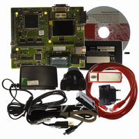
R0K572030S000BE Renesas Electronics America, R0K572030S000BE Datasheet - Page 1255

R0K572030S000BE
Manufacturer Part Number
R0K572030S000BE
Description
KIT DEV FOR SH7203
Manufacturer
Renesas Electronics America
Series
Renesas Starter Kits (RSK)r
Type
MCUr
Specifications of R0K572030S000BE
Contents
CPU Board, LCD Module, E10A-Lite Emulator, Cable, QuickStart Guide and CD-ROM
Silicon Manufacturer
Renesas
Kit Contents
Board
Silicon Family Name
SH7203
Silicon Core Number
R5S72030W200FP
Tool / Board Applications
General Purpose MCU, MPU, DSP, DSC
Mcu Supported Families
SH7203
Lead Free Status / RoHS Status
Contains lead / RoHS non-compliant
For Use With/related Products
SH7203
Lead Free Status / Rohs Status
Compliant
- Current page: 1255 of 1686
- Download datasheet (10Mb)
After the interval counter has been initialized, the counter is started under the following conditions
1 or 2 when a packet has been transferred normally.
1. An SOF is received following transmission of data in response to an IN token, in the PID =
2. An SOF is received after data following an OUT token is received in the PID = BUF state.
The interval counter is not initialized under the conditions noted below.
1. When the PID bit is set to NAK or STALL
2. The USB is suspended
(4)
With isochronous data transmission using this module in function controller function, after data
has been written to the buffer memory, a data packet can be sent with the next frame in which an
SOF packet is detected. This function is called the isochronous transfer transmission data setup
function, and it makes it possible to designate the frame from which transmission began.
If a double buffer is used for the buffer memory, transmission will be enabled for only one of the
two buffers even after the writing of data to both buffers has been completed, that buffer memory
being the one to which the data writing was completed first. For this reason, even if multiple IN
tokens are received, the only buffer memory that can be sent is one packet's worth of data.
When an IN token is received, if the buffer memory is in the transmission enabled state, this
module transmits the data. If the buffer memory is not in the transmission enabled state, however,
a zero-length packet is sent and an underrun error occurs.
Figure 23.17 shows an example of transmission using the isochronous transfer transmission data
setup function with this module, when IITV = 0 (every frame) has been set. Sending of a zero-
length packet is displayed in the figure as Null, in a shaded box.
BUF state.
The interval timer does not stop. This module attempts the transactions at the subsequent
interval.
The IITV bit is not initialized. When the SOF has been received, the counter is restarted from
the value prior to the reception of the SOF.
Setup of Data to be Transmitted using Isochronous Transfer when the Function
Controller Function is Selected
Section 23 USB 2.0 Host/Function Module (USB)
Rev. 3.00 Sep. 28, 2009 Page 1223 of 1650
REJ09B0313-0300
Related parts for R0K572030S000BE
Image
Part Number
Description
Manufacturer
Datasheet
Request
R

Part Number:
Description:
KIT STARTER FOR M16C/29
Manufacturer:
Renesas Electronics America
Datasheet:

Part Number:
Description:
KIT STARTER FOR R8C/2D
Manufacturer:
Renesas Electronics America
Datasheet:

Part Number:
Description:
R0K33062P STARTER KIT
Manufacturer:
Renesas Electronics America
Datasheet:

Part Number:
Description:
KIT STARTER FOR R8C/23 E8A
Manufacturer:
Renesas Electronics America
Datasheet:

Part Number:
Description:
KIT STARTER FOR R8C/25
Manufacturer:
Renesas Electronics America
Datasheet:

Part Number:
Description:
KIT STARTER H8S2456 SHARPE DSPLY
Manufacturer:
Renesas Electronics America
Datasheet:

Part Number:
Description:
KIT STARTER FOR R8C38C
Manufacturer:
Renesas Electronics America
Datasheet:

Part Number:
Description:
KIT STARTER FOR R8C35C
Manufacturer:
Renesas Electronics America
Datasheet:

Part Number:
Description:
KIT STARTER FOR R8CL3AC+LCD APPS
Manufacturer:
Renesas Electronics America
Datasheet:

Part Number:
Description:
KIT STARTER FOR RX610
Manufacturer:
Renesas Electronics America
Datasheet:

Part Number:
Description:
KIT STARTER FOR R32C/118
Manufacturer:
Renesas Electronics America
Datasheet:

Part Number:
Description:
KIT DEV RSK-R8C/26-29
Manufacturer:
Renesas Electronics America
Datasheet:

Part Number:
Description:
KIT STARTER FOR SH7124
Manufacturer:
Renesas Electronics America
Datasheet:

Part Number:
Description:
KIT STARTER FOR H8SX/1622
Manufacturer:
Renesas Electronics America
Datasheet:

Part Number:
Description:
KIT STARTER FOR R8C/18191A1B
Manufacturer:
Renesas Electronics America
Datasheet:


