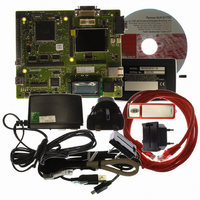
R0K572030S000BE Renesas Electronics America, R0K572030S000BE Datasheet - Page 1278

R0K572030S000BE
Manufacturer Part Number
R0K572030S000BE
Description
KIT DEV FOR SH7203
Manufacturer
Renesas Electronics America
Series
Renesas Starter Kits (RSK)r
Type
MCUr
Specifications of R0K572030S000BE
Contents
CPU Board, LCD Module, E10A-Lite Emulator, Cable, QuickStart Guide and CD-ROM
Silicon Manufacturer
Renesas
Kit Contents
Board
Silicon Family Name
SH7203
Silicon Core Number
R5S72030W200FP
Tool / Board Applications
General Purpose MCU, MPU, DSP, DSC
Mcu Supported Families
SH7203
Lead Free Status / RoHS Status
Contains lead / RoHS non-compliant
For Use With/related Products
SH7203
Lead Free Status / Rohs Status
Compliant
- Current page: 1278 of 1686
- Download datasheet (10Mb)
Section 24 LCD Controller (LCDC)
24.3.5
LDSARU sets the start address from which data is fetched by the LCDC for display of the LCDC
panel. When a DSTN panel is used, this register specifies the fetch start address for the upper side
of the panel. The register setting is updated with the Vsync timing when the LCDC is active.
Initial value:
Initial value:
Notes: 1. The minimum alignment unit of LDSARU is 512 bytes when the hardware rotation
Rev. 3.00 Sep. 28, 2009 Page 1246 of 1650
REJ09B0313-0300
Bit
31 to 28
27, 26
25 to 4
3 to 0
R/W:
R/W:
Bit:
Bit:
2. When the hardware rotation function is used (ROT = 1), set the upper-left address of
SAU15 SAU14 SAU13 SAU12 SAU11 SAU10 SAU9
LCDC Start Address Register for Upper Display Data Fetch (LDSARU)
R/W
31
15
R
0
0
-
Bit Name
⎯
⎯
SAU25 to
SAU4
⎯
function is not used. Write 0 to the lower nine bits. When using the hardware rotation
function, set the LDSARU value so that the upper-left address of the image is aligned
with the 512-byte boundary.
the image which can be calculated from the display image size in this register. The
equation below shows how to calculate the LDSARU value when the image size is 240
× 320 and LDLAOR = 256. The LDSARU value is obtained not from the panel size but
from the memory size of the image to be displayed. Note that LDLAOR must be a
binary exponential at least as large as the horizontal width of the image. Calculate
backwards using the LDSARU value (LDSARU − 256 (LDLAOR value) × (320 − 1)) to
ensure that the upper-left address of the image is aligned with the 512-byte boundary.
LDSARU = (upper-left address of image) + 256 (LDLAOR value) × 319 (line)
R/W
30
14
R
0
0
-
R/W
29
13
R
0
0
-
Initial
Value
All 0
All 1
All 0
All 0
R/W
28
12
R
0
0
-
R/W
27
11
R
1
0
-
R/W
R
R
R/W
R
R/W
26
10
R
1
0
-
SAU25 SAU24 SAU23 SAU22 SAU21 SAU20 SAU19 SAU18 SAU17 SAU16
Description
Reserved
These bits are always read as 0. The write value should
always be 0.
Reserved
These bits are always read as 1. The write value should
always be 1.
Start Address for Upper Display Data Fetch
The start address for data fetch of the display data must
be set within the synchronous DRAM area of area 3.
Reserved
These bits are always read as 0. The write value should
always be 0.
R/W
R/W
25
0
9
0
SAU8
R/W
R/W
24
0
8
0
SAU7
R/W
R/W
23
0
7
0
SAU6
R/W
R/W
22
0
6
0
SAU5
R/W
R/W
21
0
5
0
SAU4
R/W
R/W
20
0
4
0
R/W
19
R
0
3
0
-
R/W
18
R
0
2
0
-
R/W
17
R
0
1
0
-
R/W
16
R
0
0
0
-
Related parts for R0K572030S000BE
Image
Part Number
Description
Manufacturer
Datasheet
Request
R

Part Number:
Description:
KIT STARTER FOR M16C/29
Manufacturer:
Renesas Electronics America
Datasheet:

Part Number:
Description:
KIT STARTER FOR R8C/2D
Manufacturer:
Renesas Electronics America
Datasheet:

Part Number:
Description:
R0K33062P STARTER KIT
Manufacturer:
Renesas Electronics America
Datasheet:

Part Number:
Description:
KIT STARTER FOR R8C/23 E8A
Manufacturer:
Renesas Electronics America
Datasheet:

Part Number:
Description:
KIT STARTER FOR R8C/25
Manufacturer:
Renesas Electronics America
Datasheet:

Part Number:
Description:
KIT STARTER H8S2456 SHARPE DSPLY
Manufacturer:
Renesas Electronics America
Datasheet:

Part Number:
Description:
KIT STARTER FOR R8C38C
Manufacturer:
Renesas Electronics America
Datasheet:

Part Number:
Description:
KIT STARTER FOR R8C35C
Manufacturer:
Renesas Electronics America
Datasheet:

Part Number:
Description:
KIT STARTER FOR R8CL3AC+LCD APPS
Manufacturer:
Renesas Electronics America
Datasheet:

Part Number:
Description:
KIT STARTER FOR RX610
Manufacturer:
Renesas Electronics America
Datasheet:

Part Number:
Description:
KIT STARTER FOR R32C/118
Manufacturer:
Renesas Electronics America
Datasheet:

Part Number:
Description:
KIT DEV RSK-R8C/26-29
Manufacturer:
Renesas Electronics America
Datasheet:

Part Number:
Description:
KIT STARTER FOR SH7124
Manufacturer:
Renesas Electronics America
Datasheet:

Part Number:
Description:
KIT STARTER FOR H8SX/1622
Manufacturer:
Renesas Electronics America
Datasheet:

Part Number:
Description:
KIT STARTER FOR R8C/18191A1B
Manufacturer:
Renesas Electronics America
Datasheet:


