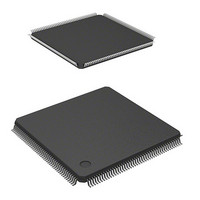
DS72011RB120FPV Renesas Electronics America, DS72011RB120FPV Datasheet - Page 14

DS72011RB120FPV
Manufacturer Part Number
DS72011RB120FPV
Description
IC SH7201 MPU ROMLESS 176LQFP
Manufacturer
Renesas Electronics America
Series
SuperH® SH7200r
Datasheet
1.R0K572011S000BE.pdf
(1222 pages)
Specifications of DS72011RB120FPV
Core Size
32-Bit
Core Processor
SH-2A
Speed
120MHz
Connectivity
CAN, EBI/EMI, FIFO, I²C, SCI, Serial Sound
Peripherals
DMA, POR, PWM, WDT
Number Of I /o
104
Program Memory Type
ROMless
Ram Size
32K x 8
Voltage - Supply (vcc/vdd)
3 V ~ 3.6 V
Data Converters
A/D 8x10b; D/A 2x8b
Oscillator Type
Internal
Operating Temperature
-20°C ~ 70°C
Package / Case
176-LQFP
No. Of I/o's
109
Ram Memory Size
32KB
Cpu Speed
120MHz
Digital Ic Case Style
LQFP
Supply Voltage Range
3V To 3.6V
Operating Temperature Range
-20°C To +70°C
Embedded Interface Type
I2C, SSI
Rohs Compliant
Yes
Lead Free Status / RoHS Status
Lead free / RoHS Compliant
For Use With
R0K572011S000BE - KIT STARTER FOR SH7201HS0005KCU11H - EMULATOR E10A-USB H8S(X),SH2(A)
Eeprom Size
-
Program Memory Size
-
Lead Free Status / RoHS Status
Lead free / RoHS Compliant, Lead free / RoHS Compliant
Available stocks
Company
Part Number
Manufacturer
Quantity
Price
Company:
Part Number:
DS72011RB120FPV
Manufacturer:
Renesas Electronics America
Quantity:
10 000
- Current page: 14 of 1222
- Download datasheet (8Mb)
9.5
9.6
Section 10 Bus Monitor..................................................................................... 285
10.1
10.2
10.3
Page xiv of xxviii
9.4.3
9.4.4
9.4.5
9.4.6
9.4.7
9.4.8
9.4.9
9.4.10
9.4.11
9.4.12
9.4.13
9.4.14
9.4.15
9.4.16
9.4.17
9.4.18
Operation .......................................................................................................................... 237
9.5.1
9.5.2
Usage Note........................................................................................................................ 283
9.6.1
9.6.2
9.6.3
Register Descriptions........................................................................................................ 285
10.1.1
10.1.2
10.1.3
10.1.4
Bus Monitor Function....................................................................................................... 293
10.2.1
10.2.2
10.2.3
10.2.4
Usage Note........................................................................................................................ 298
10.3.1
SDRAMCm Control Register (SDCmCNT) (m = 0, 1).................................... 211
CSn Mode Register (CSMODn) (n = 0 to 6) .................................................... 212
CSn Wait Control Register 1 (CS1WCNTn) (n = 0 to 6) ................................. 215
CSn Wait Control Register 2 (CS2WCNTn) (n = 0 to 6) ................................. 217
SDRAM Refresh Control Register 0 (SDRFCNT0) ......................................... 220
SDRAM Refresh Control Register 1 (SDRFCNT1) ......................................... 221
SDRAM Initialization Register 0 (SDIR0) ....................................................... 223
SDRAM Initialization Register 1 (SDIR1) ....................................................... 225
SDRAM Power-Down Control Register (SDPWDCNT) ................................. 226
SDRAM Deep-Power-Down Control Register (SDDPWDCNT)..................... 227
SDRAMm Address Register (SDmADR) (m = 0, 1)........................................ 228
SDRAMm Timing Register (SDmTR) (m = 0, 1) ............................................ 229
SDRAMm Mode Register (SDmMOD) (m = 0, 1)........................................... 231
SDRAM Status Register (SDSTR) ................................................................... 232
SDRAM Clock Stop Control Signal Setting Register (SDCKSCNT) .............. 234
AC Characteristics Switching Register (ACSWR) ........................................... 236
CSC Interface.................................................................................................... 237
SDRAM Interface ............................................................................................. 247
Note on Power-on Reset Exception Handling and Deep Standby Mode
Cancellation ...................................................................................................... 283
Write Buffer...................................................................................................... 283
Note on Transition to Software Standby Mode or Deep Standby Mode........... 283
Bus Monitor Enable Register (SYCBEEN) ...................................................... 286
Bus Monitor Status Register 1 (SYCBESTS1) ................................................. 287
Bus Monitor Status Register 2 (SYCBESTS2) ................................................. 289
Bus Error Control Register (SYCBESW) ......................................................... 292
Operation when a Bus Error is Detected........................................................... 293
Illegal Address Access Detection Function ...................................................... 294
Bus Timeout Detection Function ...................................................................... 296
Combinations of Masters and Bus Errors ......................................................... 297
Operation when the CPU is Not Notified of a Bus Error.................................. 298
R01UH0026EJ0300 Rev. 3.00
Sep 24, 2010
Related parts for DS72011RB120FPV
Image
Part Number
Description
Manufacturer
Datasheet
Request
R

Part Number:
Description:
KIT STARTER FOR M16C/29
Manufacturer:
Renesas Electronics America
Datasheet:

Part Number:
Description:
KIT STARTER FOR R8C/2D
Manufacturer:
Renesas Electronics America
Datasheet:

Part Number:
Description:
R0K33062P STARTER KIT
Manufacturer:
Renesas Electronics America
Datasheet:

Part Number:
Description:
KIT STARTER FOR R8C/23 E8A
Manufacturer:
Renesas Electronics America
Datasheet:

Part Number:
Description:
KIT STARTER FOR R8C/25
Manufacturer:
Renesas Electronics America
Datasheet:

Part Number:
Description:
KIT STARTER H8S2456 SHARPE DSPLY
Manufacturer:
Renesas Electronics America
Datasheet:

Part Number:
Description:
KIT STARTER FOR R8C38C
Manufacturer:
Renesas Electronics America
Datasheet:

Part Number:
Description:
KIT STARTER FOR R8C35C
Manufacturer:
Renesas Electronics America
Datasheet:

Part Number:
Description:
KIT STARTER FOR R8CL3AC+LCD APPS
Manufacturer:
Renesas Electronics America
Datasheet:

Part Number:
Description:
KIT STARTER FOR RX610
Manufacturer:
Renesas Electronics America
Datasheet:

Part Number:
Description:
KIT STARTER FOR R32C/118
Manufacturer:
Renesas Electronics America
Datasheet:

Part Number:
Description:
KIT DEV RSK-R8C/26-29
Manufacturer:
Renesas Electronics America
Datasheet:

Part Number:
Description:
KIT STARTER FOR SH7124
Manufacturer:
Renesas Electronics America
Datasheet:

Part Number:
Description:
KIT STARTER FOR H8SX/1622
Manufacturer:
Renesas Electronics America
Datasheet:

Part Number:
Description:
KIT DEV FOR SH7203
Manufacturer:
Renesas Electronics America
Datasheet:


