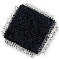
MC56F8257MLH Freescale Semiconductor, MC56F8257MLH Datasheet - Page 96

MC56F8257MLH
Manufacturer Part Number
MC56F8257MLH
Description
DSC 64K FLASH 60MHZ 64-LQFP
Manufacturer
Freescale Semiconductor
Series
56F8xxxr
Datasheets
1.TWR-56F8257.pdf
(88 pages)
2.MC56F8245VLD.pdf
(14 pages)
3.MC56F8245VLD.pdf
(2 pages)
4.MC56F8245VLD.pdf
(629 pages)
Specifications of MC56F8257MLH
Core Processor
56800E
Core Size
16-Bit
Speed
60MHz
Connectivity
CAN, I²C, LIN, SCI, SPI
Peripherals
LVD, POR, PWM, WDT
Number Of I /o
54
Program Memory Size
64KB (32K x 16)
Program Memory Type
FLASH
Ram Size
4K x 16
Voltage - Supply (vcc/vdd)
3 V ~ 3.6 V
Data Converters
A/D 16x12b, D/A 1x12b
Oscillator Type
Internal
Operating Temperature
-40°C ~ 105°C
Package / Case
64-LQFP
Product
DSCs
Processor Series
56800E
Core
56800E
Device Million Instructions Per Second
60 MIPs
Maximum Clock Frequency
60 MHz
Number Of Programmable I/os
54
Data Ram Size
8 KB
Operating Supply Voltage
3.3 V
Maximum Operating Temperature
+ 105 C
Mounting Style
SMD/SMT
Minimum Operating Temperature
- 40 C
On-chip Adc
12 bit, 8 Channel
Lead Free Status / RoHS Status
Lead free / RoHS Compliant
Eeprom Size
-
Lead Free Status / Rohs Status
Details
Available stocks
Company
Part Number
Manufacturer
Quantity
Price
Company:
Part Number:
MC56F8257MLH
Manufacturer:
MOTOLOLA
Quantity:
560
Company:
Part Number:
MC56F8257MLH
Manufacturer:
Freescale Semiconductor
Quantity:
10 000
- TWR-56F8257 PDF datasheet
- MC56F8245VLD PDF datasheet #2
- MC56F8245VLD PDF datasheet #3
- MC56F8245VLD PDF datasheet #4
- Current page: 96 of 629
- Download datasheet (4Mb)
Interrupts
2.7 Interrupts
The following table summarizes the ADC interrupts.
ADC interrupts fall into two categories:
2.8 Timing Specifications
The following figure shows a timing diagram for the ADC module. The ADC is assumed
to be in Once or Triggered mode, so the ADC clock is shown in the OFF state prior to the
SYNC pulse or START bit write. The ADC clock restarts (switching high) within 1 to 2
IP bus clocks of that event. ADC_CLK is derived from the ROSC or PLL output. The
frequency relationship is programmable. Conversions are pipelined. The second start
command is ignored because the ADC is busy with the previous start request. The third
96
• Threshold interrupts, which are caused by three different events. All of these
• Conversion complete interrupts, which are generated upon completion of any scan
ADC_ERR_INT_B
ADC_CC0_INT_B
ADC_CC1_INT_B
interrupts are optional and enabled through control register CTRL1:
and convert sequence when CTRL1[EOSIE0]=1. Additional bits may need to be set
in the Interrupt Control Module to enable the CPU to receive the interrupt signal.
Interrupt
• Zero crossing — occurs if the current result value has a sign change from the
• Low limit exceeded error — occurs when the current result value is less than the
• High limit exceeded error — is asserted if the current result value is greater than
previous result as configured by the ZXCTRL register.
low limit register value. The raw result value is compared to LOLIM[LLMT]
before the offset register value is subtracted.
the high limit register value. The raw result value is compared to HILIM[HLMT]
before the offset register value is subtracted.
STAT[LLMTI],
STAT[HLMTI]
STAT[EOSI0]
STAT[EOSI1]
MC56F825x/4x Reference Manual, Rev. 2, 10/2010
STAT[[ZCI],
Source
Table 2-70. Interrupt Summary
Zero Crossing, low Limit, and high limit interrupt
Conversion Complete Interrupt for any scan type except converter B
scan in non-simultaneous parallel scan mode (see EOSI0)
Conversion Complete Interrupt for converter B scan in non-simultane‐
ous parallel scan mode (see EOSI1)
Description
Preliminary
Freescale Semiconductor
Related parts for MC56F8257MLH
Image
Part Number
Description
Manufacturer
Datasheet
Request
R
Part Number:
Description:
Manufacturer:
Freescale Semiconductor, Inc
Datasheet:
Part Number:
Description:
Manufacturer:
Freescale Semiconductor, Inc
Datasheet:
Part Number:
Description:
Manufacturer:
Freescale Semiconductor, Inc
Datasheet:
Part Number:
Description:
Manufacturer:
Freescale Semiconductor, Inc
Datasheet:
Part Number:
Description:
Manufacturer:
Freescale Semiconductor, Inc
Datasheet:
Part Number:
Description:
Manufacturer:
Freescale Semiconductor, Inc
Datasheet:
Part Number:
Description:
Manufacturer:
Freescale Semiconductor, Inc
Datasheet:
Part Number:
Description:
Manufacturer:
Freescale Semiconductor, Inc
Datasheet:
Part Number:
Description:
Manufacturer:
Freescale Semiconductor, Inc
Datasheet:
Part Number:
Description:
Manufacturer:
Freescale Semiconductor, Inc
Datasheet:
Part Number:
Description:
Manufacturer:
Freescale Semiconductor, Inc
Datasheet:
Part Number:
Description:
Manufacturer:
Freescale Semiconductor, Inc
Datasheet:
Part Number:
Description:
Manufacturer:
Freescale Semiconductor, Inc
Datasheet:
Part Number:
Description:
Manufacturer:
Freescale Semiconductor, Inc
Datasheet:
Part Number:
Description:
Manufacturer:
Freescale Semiconductor, Inc
Datasheet:


