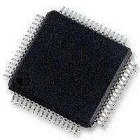
MC56F8257MLH Freescale Semiconductor, MC56F8257MLH Datasheet - Page 507

MC56F8257MLH
Manufacturer Part Number
MC56F8257MLH
Description
DSC 64K FLASH 60MHZ 64-LQFP
Manufacturer
Freescale Semiconductor
Series
56F8xxxr
Datasheets
1.TWR-56F8257.pdf
(88 pages)
2.MC56F8245VLD.pdf
(14 pages)
3.MC56F8245VLD.pdf
(2 pages)
4.MC56F8245VLD.pdf
(629 pages)
Specifications of MC56F8257MLH
Core Processor
56800E
Core Size
16-Bit
Speed
60MHz
Connectivity
CAN, I²C, LIN, SCI, SPI
Peripherals
LVD, POR, PWM, WDT
Number Of I /o
54
Program Memory Size
64KB (32K x 16)
Program Memory Type
FLASH
Ram Size
4K x 16
Voltage - Supply (vcc/vdd)
3 V ~ 3.6 V
Data Converters
A/D 16x12b, D/A 1x12b
Oscillator Type
Internal
Operating Temperature
-40°C ~ 105°C
Package / Case
64-LQFP
Product
DSCs
Processor Series
56800E
Core
56800E
Device Million Instructions Per Second
60 MIPs
Maximum Clock Frequency
60 MHz
Number Of Programmable I/os
54
Data Ram Size
8 KB
Operating Supply Voltage
3.3 V
Maximum Operating Temperature
+ 105 C
Mounting Style
SMD/SMT
Minimum Operating Temperature
- 40 C
On-chip Adc
12 bit, 8 Channel
Lead Free Status / RoHS Status
Lead free / RoHS Compliant
Eeprom Size
-
Lead Free Status / Rohs Status
Details
Available stocks
Company
Part Number
Manufacturer
Quantity
Price
Company:
Part Number:
MC56F8257MLH
Manufacturer:
MOTOLOLA
Quantity:
560
Company:
Part Number:
MC56F8257MLH
Manufacturer:
Freescale Semiconductor
Quantity:
10 000
- TWR-56F8257 PDF datasheet
- MC56F8245VLD PDF datasheet #2
- MC56F8245VLD PDF datasheet #3
- MC56F8245VLD PDF datasheet #4
- Current page: 507 of 629
- Download datasheet (4Mb)
14.3 Functional Description
The Interrupt Controller is a slave on the IP bus. It contains registers that allow each of
the interrupt sources to be set to one of four priority levels (excluding certain interrupts
that have fixed priority). All of the interrupt requests of a given level are priority encoded
to determine the lowest numerical value of the active interrupt requests for that level.
Within a given priority level, number 0 is the highest priority, and number n-1 (where n is
the total number of interrupt sources) is the lowest priority.
14.3.1 Normal Interrupt Handling
After the INTC determines that an interrupt is to be serviced and which interrupt has the
highest priority, an interrupt vector address is generated. Normal interrupt handling
concatenates the vector base address (VBA) and the vector number to determine the
vector address. In this way, an offset into the vector table is generated for each interrupt.
Freescale Semiconductor
Reserved
Reserved
INT_DIS
14–13
12–6
Field
VAB
IPIC
4–2
1–0
5
0
1
Interrupt Priority Level
These bits reflect the new interrupt priority level bits being sent to the Core. These bits indicate the priority
level needed for a new IRQ to interrupt the current interrupt being sent to the Core. This field is only
updated when the DSC core jumps to a new interrupt service routine.
00
01
10
11
Vector number
This field shows bits [7:1] of the Vector Address Bus used at the time the last IRQ was taken. In the case
of a fast interrupt, it shows the lower address bits of the jump address. This field is only updated when the
DSC core jumps to a new interrupt service routine.
Interrupt disable
This bit allows the user to disable all interrupts.
0
1
This read-only bitfield is reserved and always has the value one.
This read-only bitfield is reserved and always has the value zero.
No interrupt is being sent to the core.
An interrupt is being sent to the core.
Normal operation. (default)
All interrupts disabled.
Required nested exception priority levels are 0, 1, 2, or 3.
Required nested exception priority levels are 1, 2, or 3.
Required nested exception priority levels are 2 or3.
Required nested exception priority level is 3.
INTC_CTRL field descriptions (continued)
MC56F825x/4x Reference Manual, Rev. 2, 10/2010
Preliminary
Description
Chapter 14 Interrupt Controller (INTC)
507
Related parts for MC56F8257MLH
Image
Part Number
Description
Manufacturer
Datasheet
Request
R
Part Number:
Description:
Manufacturer:
Freescale Semiconductor, Inc
Datasheet:
Part Number:
Description:
Manufacturer:
Freescale Semiconductor, Inc
Datasheet:
Part Number:
Description:
Manufacturer:
Freescale Semiconductor, Inc
Datasheet:
Part Number:
Description:
Manufacturer:
Freescale Semiconductor, Inc
Datasheet:
Part Number:
Description:
Manufacturer:
Freescale Semiconductor, Inc
Datasheet:
Part Number:
Description:
Manufacturer:
Freescale Semiconductor, Inc
Datasheet:
Part Number:
Description:
Manufacturer:
Freescale Semiconductor, Inc
Datasheet:
Part Number:
Description:
Manufacturer:
Freescale Semiconductor, Inc
Datasheet:
Part Number:
Description:
Manufacturer:
Freescale Semiconductor, Inc
Datasheet:
Part Number:
Description:
Manufacturer:
Freescale Semiconductor, Inc
Datasheet:
Part Number:
Description:
Manufacturer:
Freescale Semiconductor, Inc
Datasheet:
Part Number:
Description:
Manufacturer:
Freescale Semiconductor, Inc
Datasheet:
Part Number:
Description:
Manufacturer:
Freescale Semiconductor, Inc
Datasheet:
Part Number:
Description:
Manufacturer:
Freescale Semiconductor, Inc
Datasheet:
Part Number:
Description:
Manufacturer:
Freescale Semiconductor, Inc
Datasheet:


