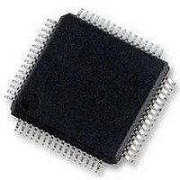
MC56F8257MLH Freescale Semiconductor, MC56F8257MLH Datasheet - Page 73

MC56F8257MLH
Manufacturer Part Number
MC56F8257MLH
Description
DSC 64K FLASH 60MHZ 64-LQFP
Manufacturer
Freescale Semiconductor
Series
56F8xxxr
Datasheets
1.TWR-56F8257.pdf
(88 pages)
2.MC56F8245VLD.pdf
(14 pages)
3.MC56F8245VLD.pdf
(2 pages)
4.MC56F8245VLD.pdf
(629 pages)
Specifications of MC56F8257MLH
Core Processor
56800E
Core Size
16-Bit
Speed
60MHz
Connectivity
CAN, I²C, LIN, SCI, SPI
Peripherals
LVD, POR, PWM, WDT
Number Of I /o
54
Program Memory Size
64KB (32K x 16)
Program Memory Type
FLASH
Ram Size
4K x 16
Voltage - Supply (vcc/vdd)
3 V ~ 3.6 V
Data Converters
A/D 16x12b, D/A 1x12b
Oscillator Type
Internal
Operating Temperature
-40°C ~ 105°C
Package / Case
64-LQFP
Product
DSCs
Processor Series
56800E
Core
56800E
Device Million Instructions Per Second
60 MIPs
Maximum Clock Frequency
60 MHz
Number Of Programmable I/os
54
Data Ram Size
8 KB
Operating Supply Voltage
3.3 V
Maximum Operating Temperature
+ 105 C
Mounting Style
SMD/SMT
Minimum Operating Temperature
- 40 C
On-chip Adc
12 bit, 8 Channel
Lead Free Status / RoHS Status
Lead free / RoHS Compliant
Eeprom Size
-
Lead Free Status / Rohs Status
Details
Available stocks
Company
Part Number
Manufacturer
Quantity
Price
Company:
Part Number:
MC56F8257MLH
Manufacturer:
MOTOLOLA
Quantity:
560
Company:
Part Number:
MC56F8257MLH
Manufacturer:
Freescale Semiconductor
Quantity:
10 000
- TWR-56F8257 PDF datasheet
- MC56F8245VLD PDF datasheet #2
- MC56F8245VLD PDF datasheet #3
- MC56F8245VLD PDF datasheet #4
- Current page: 73 of 629
- Download datasheet (4Mb)
2.3.19 ADC Calibration Register (ADC_CAL)
The ADC provides for off-chip references that can be used for ADC conversions.
Address: ADC_CAL – F080h base + 35h offset = F0B5h
Freescale Semiconductor
Reset
SEL_VREFLO_B
Read
Write
SEL_VREFH_B
Bit
Field
Field
PD0
15
14
0
15
0
14
0
When clearing this bit in any power mode except auto-powerdown (PWR[APD]=1), wait PWR[PUDELAY]
ADC clock cycles before initiating a scan to stabilize power levels within the converter. The PWR[PSTS1]
bit can be polled to determine when the PWR[PUDELAY] time has elapsed. Failure to follow this
procedure can result in loss of accuracy of the first two samples.
0
1
Manual Power Down for Converter A
This bit forces ADC converter A to power down.
Asserting this bit powers down converter A immediately. The results of a scan using converter A will be
invalid while PWR[PD0] is asserted. When PWR[PD0] is cleared, converter A is either continuously
powered up (PWR[APD] = 0) or automatically powered up when needed (PWR[APD]=1).
When clearing this bit in any power mode except auto-powerdown (PWR[APD]=1), wait PWR[PUDELAY]
ADC clock cycles before initiating a scan to stabilize power levels within the converter. The PWR[PSTS0]
bit can be polled to determine when the PWR[PUDELAY] time has elapsed. Failure to follow this
procedure can result in loss of accuracy of the first two samples.
0
1
Select V
This bit selects the source of the V
0
1
Select V
This bit selects the source of the V
Power Up ADC converter B
Power Down ADC converter B
Power Up ADC converter A
Power Down ADC converter A
Internal VDDA
ANB2
13
0
REFH
REFLO
12
0
Source
MC56F825x/4x Reference Manual, Rev. 2, 10/2010
ADC_PWR field descriptions (continued)
Source
11
0
ADC_CAL field descriptions
Table continues on the next page...
10
0
REFH
REFLO
0
9
Preliminary
reference for all conversions in converter 1.
reference for all conversions in converter 1.
0
8
0
Description
Description
0
7
0
6
Chapter 2 Analog-to-Digital Converter (ADC)
0
5
0
4
0
3
0
0
2
0
1
0
0
73
Related parts for MC56F8257MLH
Image
Part Number
Description
Manufacturer
Datasheet
Request
R
Part Number:
Description:
Manufacturer:
Freescale Semiconductor, Inc
Datasheet:
Part Number:
Description:
Manufacturer:
Freescale Semiconductor, Inc
Datasheet:
Part Number:
Description:
Manufacturer:
Freescale Semiconductor, Inc
Datasheet:
Part Number:
Description:
Manufacturer:
Freescale Semiconductor, Inc
Datasheet:
Part Number:
Description:
Manufacturer:
Freescale Semiconductor, Inc
Datasheet:
Part Number:
Description:
Manufacturer:
Freescale Semiconductor, Inc
Datasheet:
Part Number:
Description:
Manufacturer:
Freescale Semiconductor, Inc
Datasheet:
Part Number:
Description:
Manufacturer:
Freescale Semiconductor, Inc
Datasheet:
Part Number:
Description:
Manufacturer:
Freescale Semiconductor, Inc
Datasheet:
Part Number:
Description:
Manufacturer:
Freescale Semiconductor, Inc
Datasheet:
Part Number:
Description:
Manufacturer:
Freescale Semiconductor, Inc
Datasheet:
Part Number:
Description:
Manufacturer:
Freescale Semiconductor, Inc
Datasheet:
Part Number:
Description:
Manufacturer:
Freescale Semiconductor, Inc
Datasheet:
Part Number:
Description:
Manufacturer:
Freescale Semiconductor, Inc
Datasheet:
Part Number:
Description:
Manufacturer:
Freescale Semiconductor, Inc
Datasheet:


