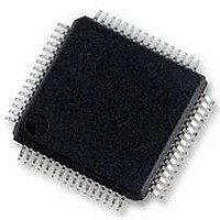
MC56F8257MLH Freescale Semiconductor, MC56F8257MLH Datasheet - Page 89

MC56F8257MLH
Manufacturer Part Number
MC56F8257MLH
Description
DSC 64K FLASH 60MHZ 64-LQFP
Manufacturer
Freescale Semiconductor
Series
56F8xxxr
Datasheets
1.TWR-56F8257.pdf
(88 pages)
2.MC56F8245VLD.pdf
(14 pages)
3.MC56F8245VLD.pdf
(2 pages)
4.MC56F8245VLD.pdf
(629 pages)
Specifications of MC56F8257MLH
Core Processor
56800E
Core Size
16-Bit
Speed
60MHz
Connectivity
CAN, I²C, LIN, SCI, SPI
Peripherals
LVD, POR, PWM, WDT
Number Of I /o
54
Program Memory Size
64KB (32K x 16)
Program Memory Type
FLASH
Ram Size
4K x 16
Voltage - Supply (vcc/vdd)
3 V ~ 3.6 V
Data Converters
A/D 16x12b, D/A 1x12b
Oscillator Type
Internal
Operating Temperature
-40°C ~ 105°C
Package / Case
64-LQFP
Product
DSCs
Processor Series
56800E
Core
56800E
Device Million Instructions Per Second
60 MIPs
Maximum Clock Frequency
60 MHz
Number Of Programmable I/os
54
Data Ram Size
8 KB
Operating Supply Voltage
3.3 V
Maximum Operating Temperature
+ 105 C
Mounting Style
SMD/SMT
Minimum Operating Temperature
- 40 C
On-chip Adc
12 bit, 8 Channel
Lead Free Status / RoHS Status
Lead free / RoHS Compliant
Eeprom Size
-
Lead Free Status / Rohs Status
Details
Available stocks
Company
Part Number
Manufacturer
Quantity
Price
Company:
Part Number:
MC56F8257MLH
Manufacturer:
MOTOLOLA
Quantity:
560
Company:
Part Number:
MC56F8257MLH
Manufacturer:
Freescale Semiconductor
Quantity:
10 000
- TWR-56F8257 PDF datasheet
- MC56F8245VLD PDF datasheet #2
- MC56F8245VLD PDF datasheet #3
- MC56F8245VLD PDF datasheet #4
- Current page: 89 of 629
- Download datasheet (4Mb)
Chapter 2 Analog-to-Digital Converter (ADC)
Figure 2-72. Result Register Data Manipulation
2.4.4 Sequential Versus Parallel Sampling
All scan modes use the sixteen sample slots in the CLIST1–4 registers. The slots are used
to define which input or differential pair to measure at each step in a scan sequence. The
SDIS register defines which sample slots are enabled. Input pairs ANA0/1, ANA2/3,
ANA4/5, ANA6/7, ANB0/1, ANB2/3, ANB4/5, and ANB6/7 can be set to be measured
differentially using the CHNCFG field. If a sample refers to an input that is not
configured as a member of a differential pair, a single-ended measurement is made. If a
sample refers to either member of a differential pair, a differential measurement is made.
Scan are either sequential or parallel. In sequential scans, up to sixteen sample slots are
sampled one at a time in order, SAMPLE [0:15]. Each sample refers to any of the sixteen
analog inputs ANA0–ANB7, so the same input can be referenced by more than one
sample slot. Only SAMPLE[0:7] have the full functionality of offset subtraction and
high/low limit compare. SAMPLE[8:15] only store the raw conversion results. Scanning
is initiated when the CTRL1 [START0] bit is written with a 1 or when the
CTRL1[SYNC0] bit is set and the SYNC0 input goes high. A scan ends when the first
disabled sample slot is encountered per the SDIS register. Completion of the scan triggers
the STAT[EOSI0] interrupt if the CTRL1[EOSIEN0] interrupt enable is set. The
CTRL1[START0] bit and SYNC0 input are ignored while a scan is in process. Scanning
stops and cannot be initiated when the CTRL1 [STOP0] bit is set.
MC56F825x/4x Reference Manual, Rev. 2, 10/2010
Preliminary
Freescale Semiconductor
89
Related parts for MC56F8257MLH
Image
Part Number
Description
Manufacturer
Datasheet
Request
R
Part Number:
Description:
Manufacturer:
Freescale Semiconductor, Inc
Datasheet:
Part Number:
Description:
Manufacturer:
Freescale Semiconductor, Inc
Datasheet:
Part Number:
Description:
Manufacturer:
Freescale Semiconductor, Inc
Datasheet:
Part Number:
Description:
Manufacturer:
Freescale Semiconductor, Inc
Datasheet:
Part Number:
Description:
Manufacturer:
Freescale Semiconductor, Inc
Datasheet:
Part Number:
Description:
Manufacturer:
Freescale Semiconductor, Inc
Datasheet:
Part Number:
Description:
Manufacturer:
Freescale Semiconductor, Inc
Datasheet:
Part Number:
Description:
Manufacturer:
Freescale Semiconductor, Inc
Datasheet:
Part Number:
Description:
Manufacturer:
Freescale Semiconductor, Inc
Datasheet:
Part Number:
Description:
Manufacturer:
Freescale Semiconductor, Inc
Datasheet:
Part Number:
Description:
Manufacturer:
Freescale Semiconductor, Inc
Datasheet:
Part Number:
Description:
Manufacturer:
Freescale Semiconductor, Inc
Datasheet:
Part Number:
Description:
Manufacturer:
Freescale Semiconductor, Inc
Datasheet:
Part Number:
Description:
Manufacturer:
Freescale Semiconductor, Inc
Datasheet:
Part Number:
Description:
Manufacturer:
Freescale Semiconductor, Inc
Datasheet:


