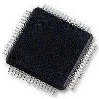
MC56F8257MLH Freescale Semiconductor, MC56F8257MLH Datasheet - Page 182

MC56F8257MLH
Manufacturer Part Number
MC56F8257MLH
Description
DSC 64K FLASH 60MHZ 64-LQFP
Manufacturer
Freescale Semiconductor
Series
56F8xxxr
Datasheets
1.TWR-56F8257.pdf
(88 pages)
2.MC56F8245VLD.pdf
(14 pages)
3.MC56F8245VLD.pdf
(2 pages)
4.MC56F8245VLD.pdf
(629 pages)
Specifications of MC56F8257MLH
Core Processor
56800E
Core Size
16-Bit
Speed
60MHz
Connectivity
CAN, I²C, LIN, SCI, SPI
Peripherals
LVD, POR, PWM, WDT
Number Of I /o
54
Program Memory Size
64KB (32K x 16)
Program Memory Type
FLASH
Ram Size
4K x 16
Voltage - Supply (vcc/vdd)
3 V ~ 3.6 V
Data Converters
A/D 16x12b, D/A 1x12b
Oscillator Type
Internal
Operating Temperature
-40°C ~ 105°C
Package / Case
64-LQFP
Product
DSCs
Processor Series
56800E
Core
56800E
Device Million Instructions Per Second
60 MIPs
Maximum Clock Frequency
60 MHz
Number Of Programmable I/os
54
Data Ram Size
8 KB
Operating Supply Voltage
3.3 V
Maximum Operating Temperature
+ 105 C
Mounting Style
SMD/SMT
Minimum Operating Temperature
- 40 C
On-chip Adc
12 bit, 8 Channel
Lead Free Status / RoHS Status
Lead free / RoHS Compliant
Eeprom Size
-
Lead Free Status / Rohs Status
Details
Available stocks
Company
Part Number
Manufacturer
Quantity
Price
Company:
Part Number:
MC56F8257MLH
Manufacturer:
MOTOLOLA
Quantity:
560
Company:
Part Number:
MC56F8257MLH
Manufacturer:
Freescale Semiconductor
Quantity:
10 000
- TWR-56F8257 PDF datasheet
- MC56F8245VLD PDF datasheet #2
- MC56F8245VLD PDF datasheet #3
- MC56F8245VLD PDF datasheet #4
- Current page: 182 of 629
- Download datasheet (4Mb)
Functional Description
Example: 6.6.2.14.1 Variable Frequency PWM Mode
>
6.6.2.15 Usage of Compare Registers
The dual compare registers (COMP1 and COMP2) provide a bidirectional modulo count
capability. The COMP1 register is used when the counter is counting up, and the COMP2
register is used when the counter is counting down. Alternating compare mode is the only
exception.
The COMP1 register should be set to the desired maximum count value or FFFFh to
indicate the maximum unsigned value prior to roll-over, and the COMP2 register should
be set to the minimum count value or 0000h to indicate the minimum unsigned value
prior to roll-under.
If CTRL[OUTMODE] is set to 100, the OFLAG will toggle while using alternating
compare registers. In this variable frequency PWM mode, the COMP2 value defines the
desired pulse width of the on time, and the COMP1 register defines the off time. The
variable frequency PWM mode is defined for positive counting only.
182
//
// This example starts with an 11 msec with a 31 msec cycle.
// Assuming the chip is operating at 60 MHz, the timer use IP_bus_clk/32 as its
//
//
// Initial pulse period: 60e6/32 clocks/sec * 31 ms = 58125 total clocks in period
// Initial pulse width: 60e6/32 clocks/sec * 11 ms = 20625 clocks in pulse
//
//
// Once the initial values of COMP1/CMPLD1 and COMP2/CMPLD2 are set the pulse width
//
//
//
void PPG1_Init(void)
{
// Set compare preload operation and enable an interrupt on compare2 events.
}
setReg(TMRA0_LOAD,0);
setReg(TMRA0_CNTR,0);
/* TMRA0_SCTRL: TCF=0,TCFIE=0,TOF=0,TOFIE=0,IEF=0,IEFIE=0,IPS=0,INPUT=0,
setReg(TMRA0_SCTRL,5);
/* TMRA0_CSCTRL: TCF2EN=1,TCF1EN=0,TCF2=0,TCF1=0,CL21=0,CL20=1,CL11=1,CL10=0 */
setReg(TMRA0_CSCTRL,0x86);
setReg(TMRA0_COMP1,20625);
setReg(TMRA0_CMPLD1,20625);
setReg(TMRA0_COMP2,58125-20625);
setReg(TMRA0_CMPLD2,58125-20625);
/* TMRA0_CTRL: CM=1,PCS=0xD,SCS=0,ONCE=0,LENGTH=1,DIR=0,Co_INIT=0,OM=4 */
setRegBits(TMRA0_CTRL,0x3A24);
clock source.
can be varied by load new values of CMPLD1 and CMPLD2 on each compare interrupt.
(See Processor Expert PPG [Programmable Pulse Generator] bean.)
(See
Usage of Compare Load
Capture_Mode=0,MSTR=0,EEOF=0,VAL=0,FORCE=1,OPS=0,OEN=1 */
MC56F825x/4x Reference Manual, Rev. 2, 10/2010
Registers.)
/* Set Comparator Status and Control Register */
/* Clear load register */
/* Clear counter */
/* Set the pulse width of the off time */
/* Set the pulse width of the on time */
/* Set Status and Control Register */
/* Set the pulse width of the off time */
/* Set the pulse width of the on time */
/* Set variable PWM mode and run counter */
Preliminary
Freescale Semiconductor
Related parts for MC56F8257MLH
Image
Part Number
Description
Manufacturer
Datasheet
Request
R
Part Number:
Description:
Manufacturer:
Freescale Semiconductor, Inc
Datasheet:
Part Number:
Description:
Manufacturer:
Freescale Semiconductor, Inc
Datasheet:
Part Number:
Description:
Manufacturer:
Freescale Semiconductor, Inc
Datasheet:
Part Number:
Description:
Manufacturer:
Freescale Semiconductor, Inc
Datasheet:
Part Number:
Description:
Manufacturer:
Freescale Semiconductor, Inc
Datasheet:
Part Number:
Description:
Manufacturer:
Freescale Semiconductor, Inc
Datasheet:
Part Number:
Description:
Manufacturer:
Freescale Semiconductor, Inc
Datasheet:
Part Number:
Description:
Manufacturer:
Freescale Semiconductor, Inc
Datasheet:
Part Number:
Description:
Manufacturer:
Freescale Semiconductor, Inc
Datasheet:
Part Number:
Description:
Manufacturer:
Freescale Semiconductor, Inc
Datasheet:
Part Number:
Description:
Manufacturer:
Freescale Semiconductor, Inc
Datasheet:
Part Number:
Description:
Manufacturer:
Freescale Semiconductor, Inc
Datasheet:
Part Number:
Description:
Manufacturer:
Freescale Semiconductor, Inc
Datasheet:
Part Number:
Description:
Manufacturer:
Freescale Semiconductor, Inc
Datasheet:
Part Number:
Description:
Manufacturer:
Freescale Semiconductor, Inc
Datasheet:


