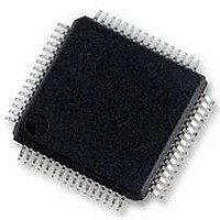
MC56F8257MLH Freescale Semiconductor, MC56F8257MLH Datasheet - Page 136

MC56F8257MLH
Manufacturer Part Number
MC56F8257MLH
Description
DSC 64K FLASH 60MHZ 64-LQFP
Manufacturer
Freescale Semiconductor
Series
56F8xxxr
Datasheets
1.TWR-56F8257.pdf
(88 pages)
2.MC56F8245VLD.pdf
(14 pages)
3.MC56F8245VLD.pdf
(2 pages)
4.MC56F8245VLD.pdf
(629 pages)
Specifications of MC56F8257MLH
Core Processor
56800E
Core Size
16-Bit
Speed
60MHz
Connectivity
CAN, I²C, LIN, SCI, SPI
Peripherals
LVD, POR, PWM, WDT
Number Of I /o
54
Program Memory Size
64KB (32K x 16)
Program Memory Type
FLASH
Ram Size
4K x 16
Voltage - Supply (vcc/vdd)
3 V ~ 3.6 V
Data Converters
A/D 16x12b, D/A 1x12b
Oscillator Type
Internal
Operating Temperature
-40°C ~ 105°C
Package / Case
64-LQFP
Product
DSCs
Processor Series
56800E
Core
56800E
Device Million Instructions Per Second
60 MIPs
Maximum Clock Frequency
60 MHz
Number Of Programmable I/os
54
Data Ram Size
8 KB
Operating Supply Voltage
3.3 V
Maximum Operating Temperature
+ 105 C
Mounting Style
SMD/SMT
Minimum Operating Temperature
- 40 C
On-chip Adc
12 bit, 8 Channel
Lead Free Status / RoHS Status
Lead free / RoHS Compliant
Eeprom Size
-
Lead Free Status / Rohs Status
Details
Available stocks
Company
Part Number
Manufacturer
Quantity
Price
Company:
Part Number:
MC56F8257MLH
Manufacturer:
MOTOLOLA
Quantity:
560
Company:
Part Number:
MC56F8257MLH
Manufacturer:
Freescale Semiconductor
Quantity:
10 000
- TWR-56F8257 PDF datasheet
- MC56F8245VLD PDF datasheet #2
- MC56F8245VLD PDF datasheet #3
- MC56F8245VLD PDF datasheet #4
- Current page: 136 of 629
- Download datasheet (4Mb)
Functional Description
5.3.1.2 Synchronous conversion mode
Data in the DAC buffered data register is controlled by the SYNC_IN signal when the
buffered data is presented to the input of the DAC. The update occurs on the rising edge
of the SYNC_IN signal. The SYNC_IN signal can come from a timer, comparators, pins,
or other sources. The CPU needs to update the buffered data register prior to the next
SYNC_IN rising edge. Otherwise, the old buffered data is reused. Note: The SYNC_IN
single must be high for at least one IPBus clock cycle and must be low for at least one
IPBus clock cycle.
5.3.2 Operation Modes
The DAC operates in either Normal or Automatic mode. In Normal mode, it generates an
analog representation of digital words. In Automatic mode, it generates sawtooth,
triangle, and square waveforms without CPU intervention.
5.3.2.1 Normal Mode
The DAC receives data words through a memory-mapped register on the IPBus (DATA).
A digital word is applied to the DAC inputs based on CTRL[SYNC_EN]. In the worst
case with no DAC output load, approximately 240 ns settling time is needed.
5.3.2.2 Automatic Mode
In Automatic mode, the DAC generates sawtooth, triangle, and square wave waveforms
without CPU intervention. The update rate, incremental step size, and minimum and
maximum values are programmable.
The value in the DATA register is used as a starting-point for the following process:
136
1. The SYNC_IN input indicates that it is time to update the data presented to the DAC.
2. The STEP value is added to/subtracted from the current DATA value and DATA is
3. If CTRL[UP] is set, then STEP is added to DATA each update until MAXVAL is
4. The generator starts subtracting STEP from DATA if CTRL[DOWN] is set (down
5. When DATA reaches MINVAL while counting down, the generator starts counting
updated.
reached.
counting enabled) or reloading MINVAL if CTRL[DOWN] is clear (no down
counting).
up if CTRL[UP] is set or reloads MAXVAL if CTRL[UP] is clear (up counting
disabled).
MC56F825x/4x Reference Manual, Rev. 2, 10/2010
Preliminary
Freescale Semiconductor
Related parts for MC56F8257MLH
Image
Part Number
Description
Manufacturer
Datasheet
Request
R
Part Number:
Description:
Manufacturer:
Freescale Semiconductor, Inc
Datasheet:
Part Number:
Description:
Manufacturer:
Freescale Semiconductor, Inc
Datasheet:
Part Number:
Description:
Manufacturer:
Freescale Semiconductor, Inc
Datasheet:
Part Number:
Description:
Manufacturer:
Freescale Semiconductor, Inc
Datasheet:
Part Number:
Description:
Manufacturer:
Freescale Semiconductor, Inc
Datasheet:
Part Number:
Description:
Manufacturer:
Freescale Semiconductor, Inc
Datasheet:
Part Number:
Description:
Manufacturer:
Freescale Semiconductor, Inc
Datasheet:
Part Number:
Description:
Manufacturer:
Freescale Semiconductor, Inc
Datasheet:
Part Number:
Description:
Manufacturer:
Freescale Semiconductor, Inc
Datasheet:
Part Number:
Description:
Manufacturer:
Freescale Semiconductor, Inc
Datasheet:
Part Number:
Description:
Manufacturer:
Freescale Semiconductor, Inc
Datasheet:
Part Number:
Description:
Manufacturer:
Freescale Semiconductor, Inc
Datasheet:
Part Number:
Description:
Manufacturer:
Freescale Semiconductor, Inc
Datasheet:
Part Number:
Description:
Manufacturer:
Freescale Semiconductor, Inc
Datasheet:
Part Number:
Description:
Manufacturer:
Freescale Semiconductor, Inc
Datasheet:


