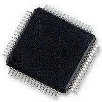
MC56F8257MLH Freescale Semiconductor, MC56F8257MLH Datasheet - Page 93

MC56F8257MLH
Manufacturer Part Number
MC56F8257MLH
Description
DSC 64K FLASH 60MHZ 64-LQFP
Manufacturer
Freescale Semiconductor
Series
56F8xxxr
Datasheets
1.TWR-56F8257.pdf
(88 pages)
2.MC56F8245VLD.pdf
(14 pages)
3.MC56F8245VLD.pdf
(2 pages)
4.MC56F8245VLD.pdf
(629 pages)
Specifications of MC56F8257MLH
Core Processor
56800E
Core Size
16-Bit
Speed
60MHz
Connectivity
CAN, I²C, LIN, SCI, SPI
Peripherals
LVD, POR, PWM, WDT
Number Of I /o
54
Program Memory Size
64KB (32K x 16)
Program Memory Type
FLASH
Ram Size
4K x 16
Voltage - Supply (vcc/vdd)
3 V ~ 3.6 V
Data Converters
A/D 16x12b, D/A 1x12b
Oscillator Type
Internal
Operating Temperature
-40°C ~ 105°C
Package / Case
64-LQFP
Product
DSCs
Processor Series
56800E
Core
56800E
Device Million Instructions Per Second
60 MIPs
Maximum Clock Frequency
60 MHz
Number Of Programmable I/os
54
Data Ram Size
8 KB
Operating Supply Voltage
3.3 V
Maximum Operating Temperature
+ 105 C
Mounting Style
SMD/SMT
Minimum Operating Temperature
- 40 C
On-chip Adc
12 bit, 8 Channel
Lead Free Status / RoHS Status
Lead free / RoHS Compliant
Eeprom Size
-
Lead Free Status / Rohs Status
Details
Available stocks
Company
Part Number
Manufacturer
Quantity
Price
Company:
Part Number:
MC56F8257MLH
Manufacturer:
MOTOLOLA
Quantity:
560
Company:
Part Number:
MC56F8257MLH
Manufacturer:
Freescale Semiconductor
Quantity:
10 000
- TWR-56F8257 PDF datasheet
- MC56F8245VLD PDF datasheet #2
- MC56F8245VLD PDF datasheet #3
- MC56F8245VLD PDF datasheet #4
- Current page: 93 of 629
- Download datasheet (4Mb)
Normal mode does not use PWR[PUDELAY] at start of scan, so no further delay is
imposed.
To start up in auto-standby, use the normal mode startup procedure first. Before starting
scan operations, set PWR[PUDELAY] to the moderate standby recovery value, and set
PWR[ASB]. Auto- standby mode automatically reduces current levels until active and
then imposes the PWR[PUDELAY] to allow current levels to rise from standby to full
power levels.
To start up in auto powerdown mode, perform the following steps:
Converters remain powered off until scanning goes active. Before a scan starts, there is a
large PWR [PUDELAY] to go from the powered down to the fully powered state.
To avoid ambiguity and ensure that the proper delays are applied when powering up or
starting scans, both regulators should be powered off (PWR[PD0]=PWR[PD1]=1) when
the clock or power controls are configured.
Attempts to start a scan during the PWR[PUDELAY] are ignored until the appropriate
PWR[PSTSn] bits are cleared.
Any attempt to use a converter when it is powered down or with the voltage references
disabled will result in invalid results. It IS possible to read ADC result registers after
converter power down for results calculated before power-down. A new scan sequence
must be started with a SYNC pulse or a write to the START bit before new valid results
are available.
In auto-powerdown mode, when the ADC goes from idle to active, a converter is
powered up only if it is required for the scan as determined by the CLIST1-4 and SDIS
registers.
2.4.6.3 Stop Mode of Operation
Any conversion sequence can be stopped by setting the relevant STOP bit. Any further
sync pulses or writes to the start bit are ignored until the STOP bit is cleared. In stop
mode, the results registers can be modified by writes from the processor. Any write to the
result register in the ADC-STOP mode is treated as if the analog core supplied the data,
so limit checking and zero crossing and associated interrupts can occur if enabled.
Freescale Semiconductor
1. Set PWR[PUDELAY] to the large power-up value.
2. Clear PWR[ASB] and set PWR[APD].
3. Clear the PWR[PD0 and/or PD1] bits for the required converters.
MC56F825x/4x Reference Manual, Rev. 2, 10/2010
Preliminary
Chapter 2 Analog-to-Digital Converter (ADC)
93
Related parts for MC56F8257MLH
Image
Part Number
Description
Manufacturer
Datasheet
Request
R
Part Number:
Description:
Manufacturer:
Freescale Semiconductor, Inc
Datasheet:
Part Number:
Description:
Manufacturer:
Freescale Semiconductor, Inc
Datasheet:
Part Number:
Description:
Manufacturer:
Freescale Semiconductor, Inc
Datasheet:
Part Number:
Description:
Manufacturer:
Freescale Semiconductor, Inc
Datasheet:
Part Number:
Description:
Manufacturer:
Freescale Semiconductor, Inc
Datasheet:
Part Number:
Description:
Manufacturer:
Freescale Semiconductor, Inc
Datasheet:
Part Number:
Description:
Manufacturer:
Freescale Semiconductor, Inc
Datasheet:
Part Number:
Description:
Manufacturer:
Freescale Semiconductor, Inc
Datasheet:
Part Number:
Description:
Manufacturer:
Freescale Semiconductor, Inc
Datasheet:
Part Number:
Description:
Manufacturer:
Freescale Semiconductor, Inc
Datasheet:
Part Number:
Description:
Manufacturer:
Freescale Semiconductor, Inc
Datasheet:
Part Number:
Description:
Manufacturer:
Freescale Semiconductor, Inc
Datasheet:
Part Number:
Description:
Manufacturer:
Freescale Semiconductor, Inc
Datasheet:
Part Number:
Description:
Manufacturer:
Freescale Semiconductor, Inc
Datasheet:
Part Number:
Description:
Manufacturer:
Freescale Semiconductor, Inc
Datasheet:


