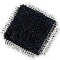
MC56F8257MLH Freescale Semiconductor, MC56F8257MLH Datasheet - Page 393

MC56F8257MLH
Manufacturer Part Number
MC56F8257MLH
Description
DSC 64K FLASH 60MHZ 64-LQFP
Manufacturer
Freescale Semiconductor
Series
56F8xxxr
Datasheets
1.TWR-56F8257.pdf
(88 pages)
2.MC56F8245VLD.pdf
(14 pages)
3.MC56F8245VLD.pdf
(2 pages)
4.MC56F8245VLD.pdf
(629 pages)
Specifications of MC56F8257MLH
Core Processor
56800E
Core Size
16-Bit
Speed
60MHz
Connectivity
CAN, I²C, LIN, SCI, SPI
Peripherals
LVD, POR, PWM, WDT
Number Of I /o
54
Program Memory Size
64KB (32K x 16)
Program Memory Type
FLASH
Ram Size
4K x 16
Voltage - Supply (vcc/vdd)
3 V ~ 3.6 V
Data Converters
A/D 16x12b, D/A 1x12b
Oscillator Type
Internal
Operating Temperature
-40°C ~ 105°C
Package / Case
64-LQFP
Product
DSCs
Processor Series
56800E
Core
56800E
Device Million Instructions Per Second
60 MIPs
Maximum Clock Frequency
60 MHz
Number Of Programmable I/os
54
Data Ram Size
8 KB
Operating Supply Voltage
3.3 V
Maximum Operating Temperature
+ 105 C
Mounting Style
SMD/SMT
Minimum Operating Temperature
- 40 C
On-chip Adc
12 bit, 8 Channel
Lead Free Status / RoHS Status
Lead free / RoHS Compliant
Eeprom Size
-
Lead Free Status / Rohs Status
Details
Available stocks
Company
Part Number
Manufacturer
Quantity
Price
Company:
Part Number:
MC56F8257MLH
Manufacturer:
MOTOLOLA
Quantity:
560
Company:
Part Number:
MC56F8257MLH
Manufacturer:
Freescale Semiconductor
Quantity:
10 000
- TWR-56F8257 PDF datasheet
- MC56F8245VLD PDF datasheet #2
- MC56F8245VLD PDF datasheet #3
- MC56F8245VLD PDF datasheet #4
- Current page: 393 of 629
- Download datasheet (4Mb)
Freescale Semiconductor
SSB_AUTO
SSB_DATA
SSB_STRB
SSB_ODM
SSB_DDR
Reserved
Reserved
SSB_IN
WOM
BD2X
Field
15
14
13
12
11
10
9
8
7
6
Wired-OR Mode
The Wired-OR mode (WOM) control bit is used to select the nature of the SPI pins. When enabled (the
WOM bit is set), the SPI pins are configured as open-drain drivers with the pull-ups disabled. When
disabled (the WOM bit is cleared), the SPI pins are configured as push-pull drivers.
This read-only bit is reserved and always has the value zero.
This read-only bit is reserved and always has the value zero.
Baud Divisor Times
When set the Baud Rate Divisor will be multiplied by 2.
SS_B Input
This read only bit shows the current state of the SS_B pin in all modes.
SS_B Data
This read/write bit is the value to drive on the SS_B pin. This bit is disabled when SSB_AUTO=1 or
SSB_STRB=1.
0
1
SS_B Open Drain Mode
This read/write bit enables open drain mode on the SS_B pin in master mode.
0
1
SS_B Automatic Mode
This read/write bit enables hardware control of the SS_B pin in master mode. (The legacy design requires
software to control the SS_B output pin.)
The initial falling edge of SS_B will be generated and SS_B will be held low until the Tx buffer or FIFO is
empty. This bit may be used alone or in combination with the SS_STRB to generate the required SS_B
signal.
0
1
SS_B Data Direction Register
This read/write bit controls input/output mode on the SS_B pin in master mode.
0
1
SS_B Strobe Mode
SS_B pin is driven low if SSB_DDR=1
SS_B pin is driven high if SSB_DDR=1
SS_B is configured for high and low drive. This mode is generally used in single master systems.
SS_B is configured as an open drain pin (only drives low output level). This mode is useful for multiple
master systems.
SS_B output signal is software generated by directly manipulating the various bits in this register or
the GPIO registers (Compatible with legacy SPI software).
SS_B output signal is hardware generated to create the initial falling edge and final rising edge. The
idle state of the SS_B is high. Do not use if MODFEN = 1.
SS_B is a configured as an input pin. Use this setting in slave mode or in master mode with
MODFEN=1.
SS_B is configured as an output pin. Use this setting in master mode with MODFEN=0.
MC56F825x/4x Reference Manual, Rev. 2, 10/2010
QSPI0_DSCTRL field descriptions
Table continues on the next page...
Preliminary
Description
Chapter 12 Queued Serial Peripheral Interface (QSPI)
393
Related parts for MC56F8257MLH
Image
Part Number
Description
Manufacturer
Datasheet
Request
R
Part Number:
Description:
Manufacturer:
Freescale Semiconductor, Inc
Datasheet:
Part Number:
Description:
Manufacturer:
Freescale Semiconductor, Inc
Datasheet:
Part Number:
Description:
Manufacturer:
Freescale Semiconductor, Inc
Datasheet:
Part Number:
Description:
Manufacturer:
Freescale Semiconductor, Inc
Datasheet:
Part Number:
Description:
Manufacturer:
Freescale Semiconductor, Inc
Datasheet:
Part Number:
Description:
Manufacturer:
Freescale Semiconductor, Inc
Datasheet:
Part Number:
Description:
Manufacturer:
Freescale Semiconductor, Inc
Datasheet:
Part Number:
Description:
Manufacturer:
Freescale Semiconductor, Inc
Datasheet:
Part Number:
Description:
Manufacturer:
Freescale Semiconductor, Inc
Datasheet:
Part Number:
Description:
Manufacturer:
Freescale Semiconductor, Inc
Datasheet:
Part Number:
Description:
Manufacturer:
Freescale Semiconductor, Inc
Datasheet:
Part Number:
Description:
Manufacturer:
Freescale Semiconductor, Inc
Datasheet:
Part Number:
Description:
Manufacturer:
Freescale Semiconductor, Inc
Datasheet:
Part Number:
Description:
Manufacturer:
Freescale Semiconductor, Inc
Datasheet:
Part Number:
Description:
Manufacturer:
Freescale Semiconductor, Inc
Datasheet:


