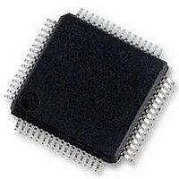
MC56F8257MLH Freescale Semiconductor, MC56F8257MLH Datasheet - Page 564

MC56F8257MLH
Manufacturer Part Number
MC56F8257MLH
Description
DSC 64K FLASH 60MHZ 64-LQFP
Manufacturer
Freescale Semiconductor
Series
56F8xxxr
Datasheets
1.TWR-56F8257.pdf
(88 pages)
2.MC56F8245VLD.pdf
(14 pages)
3.MC56F8245VLD.pdf
(2 pages)
4.MC56F8245VLD.pdf
(629 pages)
Specifications of MC56F8257MLH
Core Processor
56800E
Core Size
16-Bit
Speed
60MHz
Connectivity
CAN, I²C, LIN, SCI, SPI
Peripherals
LVD, POR, PWM, WDT
Number Of I /o
54
Program Memory Size
64KB (32K x 16)
Program Memory Type
FLASH
Ram Size
4K x 16
Voltage - Supply (vcc/vdd)
3 V ~ 3.6 V
Data Converters
A/D 16x12b, D/A 1x12b
Oscillator Type
Internal
Operating Temperature
-40°C ~ 105°C
Package / Case
64-LQFP
Product
DSCs
Processor Series
56800E
Core
56800E
Device Million Instructions Per Second
60 MIPs
Maximum Clock Frequency
60 MHz
Number Of Programmable I/os
54
Data Ram Size
8 KB
Operating Supply Voltage
3.3 V
Maximum Operating Temperature
+ 105 C
Mounting Style
SMD/SMT
Minimum Operating Temperature
- 40 C
On-chip Adc
12 bit, 8 Channel
Lead Free Status / RoHS Status
Lead free / RoHS Compliant
Eeprom Size
-
Lead Free Status / Rohs Status
Details
Available stocks
Company
Part Number
Manufacturer
Quantity
Price
Company:
Part Number:
MC56F8257MLH
Manufacturer:
MOTOLOLA
Quantity:
560
Company:
Part Number:
MC56F8257MLH
Manufacturer:
Freescale Semiconductor
Quantity:
10 000
- TWR-56F8257 PDF datasheet
- MC56F8245VLD PDF datasheet #2
- MC56F8245VLD PDF datasheet #3
- MC56F8245VLD PDF datasheet #4
- Current page: 564 of 629
- Download datasheet (4Mb)
Functional Description
Run, wait, and stop modes provide means of enabling/disabling the peripheral and/or core
clocking as a group. The stop disable controls in the SDn registers override the default
behavior of stop mode. Asserting a peripheral's stop disable bit means the peripheral's
clock continues to operate in stop mode. This option is useful for generating interrupts
that return the device from stop to run mode.
On-chip peripherals run at the IP bus clock (peripheral bus) frequency,
same as the main processor frequency in this architecture. The maximum frequency of
operation is sys_clk=60 MHz. The only exceptions are the general-purpose timers and
SCIs, which can be configured to operate at two times the system bus rate using
TMRn_CR and SCIn_CR controls.
Run, wait, and stop modes may be combined with the low power modes of the PS and
choice of clocks to provide a broad palette of power control techniques.
564
1. The TMR and PWM modules can be operated at three times the IPBus clock frequency.
Mode
Wait
Stop
Run
operational, but the SIM disables the generation
Master clock generation in the OCCS remains
Core and memory
Core and memory
System Clocks
clocks disabled
clocks enabled
of system and peripheral clocks.
Table 16-27. Clock Operation in Power Modes
MC56F825x/4x Reference Manual, Rev. 2, 10/2010
Peripheral clocks ena‐
Peripheral clocks ena‐
Peripheral Clocks
bled
bled
Preliminary
Device is fully functional
Core executes WAIT instruction to enter this mode.
Wait mode is typically used for power conscious applications.
Possible recoveries from wait mode to run mode are:
Core executes STOP instruction to enter this mode.
Possible recoveries from stop mode to run mode are:
Description
1. Any interrupt.
2. Executing a debug mode entry command using the
3. Any reset (such as POR, external, software, and COP).
1. Interrupt from any peripheral configured in SD register
2. Low voltage interrupt
3. Executing a debug mode entry command using the
4. Any reset.
DSC core JTAG interface.
to operate in stop mode.
DSC core JTAG interface.
1
Freescale Semiconductor
which is the
Related parts for MC56F8257MLH
Image
Part Number
Description
Manufacturer
Datasheet
Request
R
Part Number:
Description:
Manufacturer:
Freescale Semiconductor, Inc
Datasheet:
Part Number:
Description:
Manufacturer:
Freescale Semiconductor, Inc
Datasheet:
Part Number:
Description:
Manufacturer:
Freescale Semiconductor, Inc
Datasheet:
Part Number:
Description:
Manufacturer:
Freescale Semiconductor, Inc
Datasheet:
Part Number:
Description:
Manufacturer:
Freescale Semiconductor, Inc
Datasheet:
Part Number:
Description:
Manufacturer:
Freescale Semiconductor, Inc
Datasheet:
Part Number:
Description:
Manufacturer:
Freescale Semiconductor, Inc
Datasheet:
Part Number:
Description:
Manufacturer:
Freescale Semiconductor, Inc
Datasheet:
Part Number:
Description:
Manufacturer:
Freescale Semiconductor, Inc
Datasheet:
Part Number:
Description:
Manufacturer:
Freescale Semiconductor, Inc
Datasheet:
Part Number:
Description:
Manufacturer:
Freescale Semiconductor, Inc
Datasheet:
Part Number:
Description:
Manufacturer:
Freescale Semiconductor, Inc
Datasheet:
Part Number:
Description:
Manufacturer:
Freescale Semiconductor, Inc
Datasheet:
Part Number:
Description:
Manufacturer:
Freescale Semiconductor, Inc
Datasheet:
Part Number:
Description:
Manufacturer:
Freescale Semiconductor, Inc
Datasheet:


