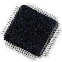
MC56F8257MLH Freescale Semiconductor, MC56F8257MLH Datasheet - Page 520

MC56F8257MLH
Manufacturer Part Number
MC56F8257MLH
Description
DSC 64K FLASH 60MHZ 64-LQFP
Manufacturer
Freescale Semiconductor
Series
56F8xxxr
Datasheets
1.TWR-56F8257.pdf
(88 pages)
2.MC56F8245VLD.pdf
(14 pages)
3.MC56F8245VLD.pdf
(2 pages)
4.MC56F8245VLD.pdf
(629 pages)
Specifications of MC56F8257MLH
Core Processor
56800E
Core Size
16-Bit
Speed
60MHz
Connectivity
CAN, I²C, LIN, SCI, SPI
Peripherals
LVD, POR, PWM, WDT
Number Of I /o
54
Program Memory Size
64KB (32K x 16)
Program Memory Type
FLASH
Ram Size
4K x 16
Voltage - Supply (vcc/vdd)
3 V ~ 3.6 V
Data Converters
A/D 16x12b, D/A 1x12b
Oscillator Type
Internal
Operating Temperature
-40°C ~ 105°C
Package / Case
64-LQFP
Product
DSCs
Processor Series
56800E
Core
56800E
Device Million Instructions Per Second
60 MIPs
Maximum Clock Frequency
60 MHz
Number Of Programmable I/os
54
Data Ram Size
8 KB
Operating Supply Voltage
3.3 V
Maximum Operating Temperature
+ 105 C
Mounting Style
SMD/SMT
Minimum Operating Temperature
- 40 C
On-chip Adc
12 bit, 8 Channel
Lead Free Status / RoHS Status
Lead free / RoHS Compliant
Eeprom Size
-
Lead Free Status / Rohs Status
Details
Available stocks
Company
Part Number
Manufacturer
Quantity
Price
Company:
Part Number:
MC56F8257MLH
Manufacturer:
MOTOLOLA
Quantity:
560
Company:
Part Number:
MC56F8257MLH
Manufacturer:
Freescale Semiconductor
Quantity:
10 000
- TWR-56F8257 PDF datasheet
- MC56F8245VLD PDF datasheet #2
- MC56F8245VLD PDF datasheet #3
- MC56F8245VLD PDF datasheet #4
- Current page: 520 of 629
- Download datasheet (4Mb)
Memory Map and Registers
15.5.2 OCCS PLL Divide-By Register (OCCS_DIVBY)
Address: OCCS_DIVBY – F120h base + 1h offset = F121h
520
Reset
Read
Write
Bit
LORTP
ZSRC
15–12
11–8
COD
Field
Field
1–0
15
0
14
0
LORTP
0
1
CLOCK Source
The CLOCK source determines the system clock source to the SIM module, which generates divided
down versions of this signal for use by memories and IP Bus. To prevent loss of reference clock to the
core, ZSRC is automatically set to 01b if PLLPD is set.
00
01
10
11
Loss of Reference Clock Trip Point
These bits control the amount of time required for the loss of reference clock interrupt to be generated.
This failure detection time is ((LORTP + 1) x 10) x (reference clock period) / (PLL
Multiplier / 2). The PLL Multiplier is set by the PLLDB register.
Clock Output Divide or Postscaler
The PLL output clock can be divided down by a 4-bit postscaler. The input of the postscaler is a
selectable clock source for the DSP core as determined by the ZSRC[1:0] in the CTRL register.
The output of the postscaler is guaranteed to be glitch free, even when COD has been changed.
NOTE: There are special restrictions on use of 2X high speed peripheral clocks.
0000
0001
0010
0011
0100
0101
0110
Relaxation Oscillator selected (reset value).
External reference selected.
Reserved
MSTR_OSC
PLL output
Reserved
13
1
Divide by one
Divide by two
Divide by four
Divide by eight
Divide by 16
divide by 32
Divide by 64
OCCS_CTRL field descriptions (continued)
12
0
MC56F825x/4x Reference Manual, Rev. 2, 10/2010
11
0
OCCS_DIVBY field descriptions
Table continues on the next page...
10
0
COD
0
9
Preliminary
0
8
Description
Description
0
0
7
0
6
0
5
1
4
PLLDB
1
3
Freescale Semiconductor
1
2
0
1
1
0
Related parts for MC56F8257MLH
Image
Part Number
Description
Manufacturer
Datasheet
Request
R
Part Number:
Description:
Manufacturer:
Freescale Semiconductor, Inc
Datasheet:
Part Number:
Description:
Manufacturer:
Freescale Semiconductor, Inc
Datasheet:
Part Number:
Description:
Manufacturer:
Freescale Semiconductor, Inc
Datasheet:
Part Number:
Description:
Manufacturer:
Freescale Semiconductor, Inc
Datasheet:
Part Number:
Description:
Manufacturer:
Freescale Semiconductor, Inc
Datasheet:
Part Number:
Description:
Manufacturer:
Freescale Semiconductor, Inc
Datasheet:
Part Number:
Description:
Manufacturer:
Freescale Semiconductor, Inc
Datasheet:
Part Number:
Description:
Manufacturer:
Freescale Semiconductor, Inc
Datasheet:
Part Number:
Description:
Manufacturer:
Freescale Semiconductor, Inc
Datasheet:
Part Number:
Description:
Manufacturer:
Freescale Semiconductor, Inc
Datasheet:
Part Number:
Description:
Manufacturer:
Freescale Semiconductor, Inc
Datasheet:
Part Number:
Description:
Manufacturer:
Freescale Semiconductor, Inc
Datasheet:
Part Number:
Description:
Manufacturer:
Freescale Semiconductor, Inc
Datasheet:
Part Number:
Description:
Manufacturer:
Freescale Semiconductor, Inc
Datasheet:
Part Number:
Description:
Manufacturer:
Freescale Semiconductor, Inc
Datasheet:


