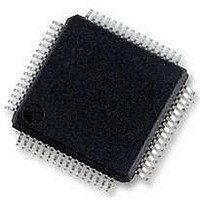
MC56F8257MLH Freescale Semiconductor, MC56F8257MLH Datasheet - Page 260

MC56F8257MLH
Manufacturer Part Number
MC56F8257MLH
Description
DSC 64K FLASH 60MHZ 64-LQFP
Manufacturer
Freescale Semiconductor
Series
56F8xxxr
Datasheets
1.TWR-56F8257.pdf
(88 pages)
2.MC56F8245VLD.pdf
(14 pages)
3.MC56F8245VLD.pdf
(2 pages)
4.MC56F8245VLD.pdf
(629 pages)
Specifications of MC56F8257MLH
Core Processor
56800E
Core Size
16-Bit
Speed
60MHz
Connectivity
CAN, I²C, LIN, SCI, SPI
Peripherals
LVD, POR, PWM, WDT
Number Of I /o
54
Program Memory Size
64KB (32K x 16)
Program Memory Type
FLASH
Ram Size
4K x 16
Voltage - Supply (vcc/vdd)
3 V ~ 3.6 V
Data Converters
A/D 16x12b, D/A 1x12b
Oscillator Type
Internal
Operating Temperature
-40°C ~ 105°C
Package / Case
64-LQFP
Product
DSCs
Processor Series
56800E
Core
56800E
Device Million Instructions Per Second
60 MIPs
Maximum Clock Frequency
60 MHz
Number Of Programmable I/os
54
Data Ram Size
8 KB
Operating Supply Voltage
3.3 V
Maximum Operating Temperature
+ 105 C
Mounting Style
SMD/SMT
Minimum Operating Temperature
- 40 C
On-chip Adc
12 bit, 8 Channel
Lead Free Status / RoHS Status
Lead free / RoHS Compliant
Eeprom Size
-
Lead Free Status / Rohs Status
Details
Available stocks
Company
Part Number
Manufacturer
Quantity
Price
Company:
Part Number:
MC56F8257MLH
Manufacturer:
MOTOLOLA
Quantity:
560
Company:
Part Number:
MC56F8257MLH
Manufacturer:
Freescale Semiconductor
Quantity:
10 000
- TWR-56F8257 PDF datasheet
- MC56F8245VLD PDF datasheet #2
- MC56F8245VLD PDF datasheet #3
- MC56F8245VLD PDF datasheet #4
- Current page: 260 of 629
- Download datasheet (4Mb)
Functional Description
The submodule timers only count in the up direction and then reset to the INIT value.
Instead of having a single value that determines pulse width, there are two values that
must be specified: the turn on edge and the turn off edge. This double action edge
generation not only gives the user control over the pulse width, but over the relative
alignment of the signal as well. As a result, there is no need to support separate PWM
alignment modes since the PWM alignment mode is inherently a function of the turn on
and turn off edge values.
Figure 7-208
also illustrates an additional enhancement to the PWM generation process.
When the counter resets, it is reloaded with a user specified value, which may or may not
be zero. If the value chosen happens to be the 2's complement of the modulus value, then
the PWM generator operates in "signed" mode. This means that if each PWM's turn on
and turn off edge values are also the same number but only different in their sign, the
"on" portion of the output signal will be centered around a count value of zero. Therefore,
only one PWM value needs to be calculated in software and then this value and its
negative are provided to the submodule as the turn off and turn on edges respectively.
This technique will result in a pulse width that always consists of an odd number of timer
counts. If all PWM signal edge calculations follow this same convention, then the signals
will be center aligned with respect to each other, which is the goal. Of course, center
alignment between the signals is not restricted to symmetry around the zero count value,
as any other number would also work. However, centering on zero provides the greatest
range in signed mode and also simplifies the calculations.
7.4.1.2 Edge Aligned PWMs
When the turn on edge for each pulse is specified to be the INIT value, then edge aligned
operation results, as the following figure shows. Therefore, only the turn off edge value
needs to be periodically updated to change the pulse width.
MC56F825x/4x Reference Manual, Rev. 2, 10/2010
Preliminary
260
Freescale Semiconductor
Related parts for MC56F8257MLH
Image
Part Number
Description
Manufacturer
Datasheet
Request
R
Part Number:
Description:
Manufacturer:
Freescale Semiconductor, Inc
Datasheet:
Part Number:
Description:
Manufacturer:
Freescale Semiconductor, Inc
Datasheet:
Part Number:
Description:
Manufacturer:
Freescale Semiconductor, Inc
Datasheet:
Part Number:
Description:
Manufacturer:
Freescale Semiconductor, Inc
Datasheet:
Part Number:
Description:
Manufacturer:
Freescale Semiconductor, Inc
Datasheet:
Part Number:
Description:
Manufacturer:
Freescale Semiconductor, Inc
Datasheet:
Part Number:
Description:
Manufacturer:
Freescale Semiconductor, Inc
Datasheet:
Part Number:
Description:
Manufacturer:
Freescale Semiconductor, Inc
Datasheet:
Part Number:
Description:
Manufacturer:
Freescale Semiconductor, Inc
Datasheet:
Part Number:
Description:
Manufacturer:
Freescale Semiconductor, Inc
Datasheet:
Part Number:
Description:
Manufacturer:
Freescale Semiconductor, Inc
Datasheet:
Part Number:
Description:
Manufacturer:
Freescale Semiconductor, Inc
Datasheet:
Part Number:
Description:
Manufacturer:
Freescale Semiconductor, Inc
Datasheet:
Part Number:
Description:
Manufacturer:
Freescale Semiconductor, Inc
Datasheet:
Part Number:
Description:
Manufacturer:
Freescale Semiconductor, Inc
Datasheet:


