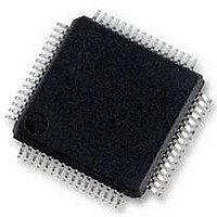
MC56F8257MLH Freescale Semiconductor, MC56F8257MLH Datasheet - Page 533

MC56F8257MLH
Manufacturer Part Number
MC56F8257MLH
Description
DSC 64K FLASH 60MHZ 64-LQFP
Manufacturer
Freescale Semiconductor
Series
56F8xxxr
Datasheets
1.TWR-56F8257.pdf
(88 pages)
2.MC56F8245VLD.pdf
(14 pages)
3.MC56F8245VLD.pdf
(2 pages)
4.MC56F8245VLD.pdf
(629 pages)
Specifications of MC56F8257MLH
Core Processor
56800E
Core Size
16-Bit
Speed
60MHz
Connectivity
CAN, I²C, LIN, SCI, SPI
Peripherals
LVD, POR, PWM, WDT
Number Of I /o
54
Program Memory Size
64KB (32K x 16)
Program Memory Type
FLASH
Ram Size
4K x 16
Voltage - Supply (vcc/vdd)
3 V ~ 3.6 V
Data Converters
A/D 16x12b, D/A 1x12b
Oscillator Type
Internal
Operating Temperature
-40°C ~ 105°C
Package / Case
64-LQFP
Product
DSCs
Processor Series
56800E
Core
56800E
Device Million Instructions Per Second
60 MIPs
Maximum Clock Frequency
60 MHz
Number Of Programmable I/os
54
Data Ram Size
8 KB
Operating Supply Voltage
3.3 V
Maximum Operating Temperature
+ 105 C
Mounting Style
SMD/SMT
Minimum Operating Temperature
- 40 C
On-chip Adc
12 bit, 8 Channel
Lead Free Status / RoHS Status
Lead free / RoHS Compliant
Eeprom Size
-
Lead Free Status / Rohs Status
Details
Available stocks
Company
Part Number
Manufacturer
Quantity
Price
Company:
Part Number:
MC56F8257MLH
Manufacturer:
MOTOLOLA
Quantity:
560
Company:
Part Number:
MC56F8257MLH
Manufacturer:
Freescale Semiconductor
Quantity:
10 000
- TWR-56F8257 PDF datasheet
- MC56F8245VLD PDF datasheet #2
- MC56F8245VLD PDF datasheet #3
- MC56F8245VLD PDF datasheet #4
- Current page: 533 of 629
- Download datasheet (4Mb)
15.9.2 PLL Frequency Lock Detector Block
This digital block monitors the VCO output clock and sets the LCK[1:0] bits in the
OCCS Status Register (STAT) based on its frequency accuracy. The lock detector is
enabled with the LCKON bit of the PLL control register (CTRL) and the CTRL[PLLPD]
bit. Once enabled, the detector starts two counters whose outputs are periodically
compared. The input clocks to these counters are the VCO output clock divided by the
value in DIVBY[PLLDB], called FEEDBACK, and the PLL input clock. The period of
the pulses being compared cover one whole period of each clock.
FEEDBACK and MSTR_OSC clocks are compared after 16, 32, and 64 cycles. If, after
32 cycles, the clocks match, the LCK0 bit is set to one. If, after 64 cycles of MSTR_OSC,
there is the same number of MSTR_OSC clocks as FEEDBACK clocks, the LCK1 bit is
also set. The LCK bits remain set until any of these events occur:
When the circuit sets the LCK1, the two counters are reset and start the count again. The
lock detector is designed so if LCK1 is reset to zero because clocks did not match, LCK0
can stay high. This provides the processor the accuracy of the two clocks with respect to
each other.
15.9.3 Loss of Reference Clock Detector
The loss of reference clock detector is designed to generate an interrupt when the
reference clock to the PLL is interrupted. An LOR interrupt should occur after a
minimum time of (LORTP+1) × 10 x (reference clock period) / ((PLLDB+1) / 2). This is
the minimum time because the PLL output frequency starts to decrease as the PLL tries
to track the input reference source. In fact, the phase locked loop can continue running
for a time after its reference clock has been disturbed. This provides time for detection of
the problem and an orderly system shutdown.
Freescale Semiconductor
• Clocks fail to match
• Reset caused by LCKON, PLLPD
• Chip-level reset
MC56F825x/4x Reference Manual, Rev. 2, 10/2010
Preliminary
Chapter 15 On-Chip Clock Synthesis (OCCS)
533
Related parts for MC56F8257MLH
Image
Part Number
Description
Manufacturer
Datasheet
Request
R
Part Number:
Description:
Manufacturer:
Freescale Semiconductor, Inc
Datasheet:
Part Number:
Description:
Manufacturer:
Freescale Semiconductor, Inc
Datasheet:
Part Number:
Description:
Manufacturer:
Freescale Semiconductor, Inc
Datasheet:
Part Number:
Description:
Manufacturer:
Freescale Semiconductor, Inc
Datasheet:
Part Number:
Description:
Manufacturer:
Freescale Semiconductor, Inc
Datasheet:
Part Number:
Description:
Manufacturer:
Freescale Semiconductor, Inc
Datasheet:
Part Number:
Description:
Manufacturer:
Freescale Semiconductor, Inc
Datasheet:
Part Number:
Description:
Manufacturer:
Freescale Semiconductor, Inc
Datasheet:
Part Number:
Description:
Manufacturer:
Freescale Semiconductor, Inc
Datasheet:
Part Number:
Description:
Manufacturer:
Freescale Semiconductor, Inc
Datasheet:
Part Number:
Description:
Manufacturer:
Freescale Semiconductor, Inc
Datasheet:
Part Number:
Description:
Manufacturer:
Freescale Semiconductor, Inc
Datasheet:
Part Number:
Description:
Manufacturer:
Freescale Semiconductor, Inc
Datasheet:
Part Number:
Description:
Manufacturer:
Freescale Semiconductor, Inc
Datasheet:
Part Number:
Description:
Manufacturer:
Freescale Semiconductor, Inc
Datasheet:


