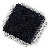
MC56F8257MLH Freescale Semiconductor, MC56F8257MLH Datasheet - Page 91

MC56F8257MLH
Manufacturer Part Number
MC56F8257MLH
Description
DSC 64K FLASH 60MHZ 64-LQFP
Manufacturer
Freescale Semiconductor
Series
56F8xxxr
Datasheets
1.TWR-56F8257.pdf
(88 pages)
2.MC56F8245VLD.pdf
(14 pages)
3.MC56F8245VLD.pdf
(2 pages)
4.MC56F8245VLD.pdf
(629 pages)
Specifications of MC56F8257MLH
Core Processor
56800E
Core Size
16-Bit
Speed
60MHz
Connectivity
CAN, I²C, LIN, SCI, SPI
Peripherals
LVD, POR, PWM, WDT
Number Of I /o
54
Program Memory Size
64KB (32K x 16)
Program Memory Type
FLASH
Ram Size
4K x 16
Voltage - Supply (vcc/vdd)
3 V ~ 3.6 V
Data Converters
A/D 16x12b, D/A 1x12b
Oscillator Type
Internal
Operating Temperature
-40°C ~ 105°C
Package / Case
64-LQFP
Product
DSCs
Processor Series
56800E
Core
56800E
Device Million Instructions Per Second
60 MIPs
Maximum Clock Frequency
60 MHz
Number Of Programmable I/os
54
Data Ram Size
8 KB
Operating Supply Voltage
3.3 V
Maximum Operating Temperature
+ 105 C
Mounting Style
SMD/SMT
Minimum Operating Temperature
- 40 C
On-chip Adc
12 bit, 8 Channel
Lead Free Status / RoHS Status
Lead free / RoHS Compliant
Eeprom Size
-
Lead Free Status / Rohs Status
Details
Available stocks
Company
Part Number
Manufacturer
Quantity
Price
Company:
Part Number:
MC56F8257MLH
Manufacturer:
MOTOLOLA
Quantity:
560
Company:
Part Number:
MC56F8257MLH
Manufacturer:
Freescale Semiconductor
Quantity:
10 000
- TWR-56F8257 PDF datasheet
- MC56F8245VLD PDF datasheet #2
- MC56F8245VLD PDF datasheet #3
- MC56F8245VLD PDF datasheet #4
- Current page: 91 of 629
- Download datasheet (4Mb)
All scan modes ignore sync pulses while a scan is in process unless the scan is paused by
the SCTRL[SC] bits. Once scan modes continue to ignore sync pulses even after the scan
completes until the CTRL*[SYNC*] bit is set again. However, a reset can occur any time
including during the scan. The SYNC0 input is re-armed by setting the CTRL1[SYNC0]
bit, and the SYNC1 input is reset by setting the CTRL2[SYNC1] bit. A reset can be
performed any time after a scan starts.
2.4.6 Power Management
The five supported power modes are are discussed in order from highest to lowest power
usage at the expense of increased conversion latency and/or startup delay. Changes to the
SIM and OCCS that affect the power modes should be made while the PWR[PD0] and
PWR[PD1] bits are both asserted. See the Clocks section for details on the various clocks
referenced here.
2.4.6.1 Low Power Modes
In the following table, the low-power modes are discussed in order from from highest to
lowest power usage.
Freescale Semiconductor
Normal power
Auto-standby
as soon as the B converter scan completes. All subsequent start and sync pulses are
ignored after the scan begins unless the scan is paused by the SCTRL[SC] bits.
Scanning can only be terminated by setting the STOP bit.
Mode
At least one ADC converter is powered up (PWR[PD0 or PD1] is 0), the PWR[APD and ASB] bits
are both 0, and the SIM_PCE[ADC] bit is 1. The ADC uses the conversion clock as the ADC clock
source in either active or idle. The conversion clock should be configured at or near 15 MHz to
minimize conversion latency although PWR2[SPEEDn] can be used for reduced power consump‐
tion when lower conversion frequencies are acceptable . No startup delay (PWR[PUDELAY]) is
imposed.
At least one ADC converter is powered up (PWR[PD0 or PD1] is 0), PWR[APD] is 0, PWR[ASB]
is 1, and the SIM_PCE[ADC] bit is 1. The OCCS MSTR_OSC signal must operate at 8 MHz.
MSTR_OSC is divided by 80 to generate a 100 kHz standby clock either using an 8 MHz external
clock source or using the ROSC as the clock source in its normal mode of operation
(ROPD=ROSB=0). The ADC uses the conversion clock when active and the 100 kHz standby
clock when idle. The standby (low current) state automatically engages when the ADC is idle. The
conversion clock should be configured at or near 15 MHz to minimize conversion latency when
active although PWR2[SPEEDn] can be used for reduced power consumption when lower con‐
version frequencies are acceptable. At the start of all scans, there is a startup delay of PWR[PU‐
DELAY] ADC clocks to engage the conversion clock and revert from standby to normal current
mode. Auto-standby is a compromise between normal and auto-powerdown modes. This mode
offers moderate power savings at the cost of a moderate latency when leaving the idle state to
start a new scan.
MC56F825x/4x Reference Manual, Rev. 2, 10/2010
Table continues on the next page...
Preliminary
Description
Chapter 2 Analog-to-Digital Converter (ADC)
91
Related parts for MC56F8257MLH
Image
Part Number
Description
Manufacturer
Datasheet
Request
R
Part Number:
Description:
Manufacturer:
Freescale Semiconductor, Inc
Datasheet:
Part Number:
Description:
Manufacturer:
Freescale Semiconductor, Inc
Datasheet:
Part Number:
Description:
Manufacturer:
Freescale Semiconductor, Inc
Datasheet:
Part Number:
Description:
Manufacturer:
Freescale Semiconductor, Inc
Datasheet:
Part Number:
Description:
Manufacturer:
Freescale Semiconductor, Inc
Datasheet:
Part Number:
Description:
Manufacturer:
Freescale Semiconductor, Inc
Datasheet:
Part Number:
Description:
Manufacturer:
Freescale Semiconductor, Inc
Datasheet:
Part Number:
Description:
Manufacturer:
Freescale Semiconductor, Inc
Datasheet:
Part Number:
Description:
Manufacturer:
Freescale Semiconductor, Inc
Datasheet:
Part Number:
Description:
Manufacturer:
Freescale Semiconductor, Inc
Datasheet:
Part Number:
Description:
Manufacturer:
Freescale Semiconductor, Inc
Datasheet:
Part Number:
Description:
Manufacturer:
Freescale Semiconductor, Inc
Datasheet:
Part Number:
Description:
Manufacturer:
Freescale Semiconductor, Inc
Datasheet:
Part Number:
Description:
Manufacturer:
Freescale Semiconductor, Inc
Datasheet:
Part Number:
Description:
Manufacturer:
Freescale Semiconductor, Inc
Datasheet:


