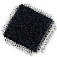
MC56F8257MLH Freescale Semiconductor, MC56F8257MLH Datasheet - Page 339

MC56F8257MLH
Manufacturer Part Number
MC56F8257MLH
Description
DSC 64K FLASH 60MHZ 64-LQFP
Manufacturer
Freescale Semiconductor
Series
56F8xxxr
Datasheets
1.TWR-56F8257.pdf
(88 pages)
2.MC56F8245VLD.pdf
(14 pages)
3.MC56F8245VLD.pdf
(2 pages)
4.MC56F8245VLD.pdf
(629 pages)
Specifications of MC56F8257MLH
Core Processor
56800E
Core Size
16-Bit
Speed
60MHz
Connectivity
CAN, I²C, LIN, SCI, SPI
Peripherals
LVD, POR, PWM, WDT
Number Of I /o
54
Program Memory Size
64KB (32K x 16)
Program Memory Type
FLASH
Ram Size
4K x 16
Voltage - Supply (vcc/vdd)
3 V ~ 3.6 V
Data Converters
A/D 16x12b, D/A 1x12b
Oscillator Type
Internal
Operating Temperature
-40°C ~ 105°C
Package / Case
64-LQFP
Product
DSCs
Processor Series
56800E
Core
56800E
Device Million Instructions Per Second
60 MIPs
Maximum Clock Frequency
60 MHz
Number Of Programmable I/os
54
Data Ram Size
8 KB
Operating Supply Voltage
3.3 V
Maximum Operating Temperature
+ 105 C
Mounting Style
SMD/SMT
Minimum Operating Temperature
- 40 C
On-chip Adc
12 bit, 8 Channel
Lead Free Status / RoHS Status
Lead free / RoHS Compliant
Eeprom Size
-
Lead Free Status / Rohs Status
Details
Available stocks
Company
Part Number
Manufacturer
Quantity
Price
Company:
Part Number:
MC56F8257MLH
Manufacturer:
MOTOLOLA
Quantity:
560
Company:
Part Number:
MC56F8257MLH
Manufacturer:
Freescale Semiconductor
Quantity:
10 000
- TWR-56F8257 PDF datasheet
- MC56F8245VLD PDF datasheet #2
- MC56F8245VLD PDF datasheet #3
- MC56F8245VLD PDF datasheet #4
- Current page: 339 of 629
- Download datasheet (4Mb)
10.4.2 10-bit Address
For 10-bit addressing, 0x11110 is used for the first 5 bits of the first address byte.
Various combinations of read/write formats are possible within a transfer that includes
10-bit addressing.
10.4.2.1 Master-Transmitter Addresses a Slave-Receiver
The transfer direction is not changed. When a 10-bit address follows a START condition,
each slave compares the first seven bits of the first byte of the slave address (11110XX)
with its own address and tests whether the eighth bit (R/W direction bit) is 0. It is
possible that more than one device finds a match and generates an acknowledge (A1).
Each slave that finds a match compares the eight bits of the second byte of the slave
address with its own address, but only one slave finds a match and generate an
acknowledge (A2). The matching slave remains addressed by the master until it receives
a STOP condition (P) or a repeated START condition (Sr) followed by a different slave
address.
After the master-transmitter has sent the first byte of the 10-bit address, the slave-receiver
sees an I2C interrupt. User software must ensure that for this interrupt, the contents of the
Data register are ignored and not treated as valid data.
10.4.2.2 Master-Receiver Addresses a Slave-Transmitter
The transfer direction is changed after the second R/W bit. Up to and including
acknowledge bit A2, the procedure is the same as that described for a master-transmitter
addressing a slave-receiver. After the repeated START condition (Sr), a matching slave
remembers that it was addressed before. This slave then checks whether the first seven
Freescale Semiconductor
S
Table 10-38. Master-Transmitter Addresses Slave-Receiver with a 10-bit
11110
Slave
AD10
+ AD9
dress
first 7
bits
ad‐
+
R/W
0
Address
MC56F825x/4x Reference Manual, Rev. 2, 10/2010
A1
second
AD[8:1]
Slave
dress
byte
ad‐
Preliminary
A2
Data
A
Chapter 10 Inter-Integrated Circuit (I2C)
...
Data
A/A
P
339
Related parts for MC56F8257MLH
Image
Part Number
Description
Manufacturer
Datasheet
Request
R
Part Number:
Description:
Manufacturer:
Freescale Semiconductor, Inc
Datasheet:
Part Number:
Description:
Manufacturer:
Freescale Semiconductor, Inc
Datasheet:
Part Number:
Description:
Manufacturer:
Freescale Semiconductor, Inc
Datasheet:
Part Number:
Description:
Manufacturer:
Freescale Semiconductor, Inc
Datasheet:
Part Number:
Description:
Manufacturer:
Freescale Semiconductor, Inc
Datasheet:
Part Number:
Description:
Manufacturer:
Freescale Semiconductor, Inc
Datasheet:
Part Number:
Description:
Manufacturer:
Freescale Semiconductor, Inc
Datasheet:
Part Number:
Description:
Manufacturer:
Freescale Semiconductor, Inc
Datasheet:
Part Number:
Description:
Manufacturer:
Freescale Semiconductor, Inc
Datasheet:
Part Number:
Description:
Manufacturer:
Freescale Semiconductor, Inc
Datasheet:
Part Number:
Description:
Manufacturer:
Freescale Semiconductor, Inc
Datasheet:
Part Number:
Description:
Manufacturer:
Freescale Semiconductor, Inc
Datasheet:
Part Number:
Description:
Manufacturer:
Freescale Semiconductor, Inc
Datasheet:
Part Number:
Description:
Manufacturer:
Freescale Semiconductor, Inc
Datasheet:
Part Number:
Description:
Manufacturer:
Freescale Semiconductor, Inc
Datasheet:


