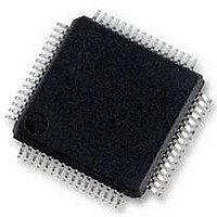
MC56F8257MLH Freescale Semiconductor, MC56F8257MLH Datasheet - Page 51

MC56F8257MLH
Manufacturer Part Number
MC56F8257MLH
Description
DSC 64K FLASH 60MHZ 64-LQFP
Manufacturer
Freescale Semiconductor
Series
56F8xxxr
Datasheets
1.TWR-56F8257.pdf
(88 pages)
2.MC56F8245VLD.pdf
(14 pages)
3.MC56F8245VLD.pdf
(2 pages)
4.MC56F8245VLD.pdf
(629 pages)
Specifications of MC56F8257MLH
Core Processor
56800E
Core Size
16-Bit
Speed
60MHz
Connectivity
CAN, I²C, LIN, SCI, SPI
Peripherals
LVD, POR, PWM, WDT
Number Of I /o
54
Program Memory Size
64KB (32K x 16)
Program Memory Type
FLASH
Ram Size
4K x 16
Voltage - Supply (vcc/vdd)
3 V ~ 3.6 V
Data Converters
A/D 16x12b, D/A 1x12b
Oscillator Type
Internal
Operating Temperature
-40°C ~ 105°C
Package / Case
64-LQFP
Product
DSCs
Processor Series
56800E
Core
56800E
Device Million Instructions Per Second
60 MIPs
Maximum Clock Frequency
60 MHz
Number Of Programmable I/os
54
Data Ram Size
8 KB
Operating Supply Voltage
3.3 V
Maximum Operating Temperature
+ 105 C
Mounting Style
SMD/SMT
Minimum Operating Temperature
- 40 C
On-chip Adc
12 bit, 8 Channel
Lead Free Status / RoHS Status
Lead free / RoHS Compliant
Eeprom Size
-
Lead Free Status / Rohs Status
Details
Available stocks
Company
Part Number
Manufacturer
Quantity
Price
Company:
Part Number:
MC56F8257MLH
Manufacturer:
MOTOLOLA
Quantity:
560
Company:
Part Number:
MC56F8257MLH
Manufacturer:
Freescale Semiconductor
Quantity:
10 000
- TWR-56F8257 PDF datasheet
- MC56F8245VLD PDF datasheet #2
- MC56F8245VLD PDF datasheet #3
- MC56F8245VLD PDF datasheet #4
- Current page: 51 of 629
- Download datasheet (4Mb)
Freescale Semiconductor
CHNCFG_H
Reserved
EOSIE1
SYNC1
Field
9–6
12
11
10
During parallel scan modes when SIMULT = 0, this bit enables start control of a B converter parallel scan.
A scan is started by writing 1 to this bit. This is a write only bit. Writing 1 to it again while the scan remains
in process, is ignored.
The ADC must be in a stable power configuration prior to writing the start bit. Refer to the functional
description of power modes for further details.
0
1
SYNC1 Enable
During parallel scan modes when CTRL2[SIMULT]=0, setting this bit to 1 permits a B converter parallel
scan to be initiated by asserting the SYNC1 input for at least one ADC clock cycle. CTRL2[SYNC1] is
cleared in ONCE mode, CTRL1[SMODE=000 or 001], when the first SYNC input is detected. This
prevents unintentionally starting a new scan after the first scan has completed.
The ADC must be in a stable power mode prior to SYNC1 input assertion. Refer to the functional
description of power modes for further details.
In "once" scan modes, only a first SYNC1 input pulse is honored. CTRL2[SYNC1] is cleared in this mode
when the first SYNC1 input is detected. This prevents unintentionally starting a new scan after the first
scan has completed. The CTRL2[SYNC1] bit can be set again at any time including while the scan
remains in process.
0
1
End Of Scan Interrupt Enable
During parallel scan modes when SIMULT = 0, this bit enables interrupt control for a B converter parallel
scan.
This bit enables an EOSI1 interrupt to be generated upon completion of the scan. For looping scan
modes, the interrupt will trigger after the completion of each iteration of the loop.
0
1
This read-only bit is reserved and always has the value zero.
CHCNF (Channel Configure High) bits
The bits configure the analog inputs for either single ended or differential conversions. Differential
measurements return the max value ((2**12)-1) when the + input is V
0 when the + input is at V
voltage difference between the two signals. Single ended measurements return the max value when the
input is at V
by which the input exceeds V
xxx1
xxx0
xx1x
xx0x
x1xx
x0xx
No action
Start command is issued
B converter parallel scan is initiated by a write to CTRL2[START1] bit only
Use a SYNC1 input pulse or CTRL2[START1] bit to initiate a B converter parallel scan
Interrupt disabled
Interrupt enabled
Inputs = ANA4-ANA5 — Configured as differential pair (ANA4 is + and ANA5 is --)
Inputs = ANA4-ANA5 — Both configured as single ended inputs
Inputs = ANA6-ANA7 — Configured as differential pair (ANA6 is + and ANA7 is --)
Inputs = ANA6-ANA7 — Both configured as single ended inputs
Inputs = ANB4-ANB5 — Configured as differential pair (ANB4 is + and ANB5 is --)
Inputs = ANB4-ANB5 — Both configured as single ended inputs
REFH
ADC_CTRL2 field descriptions (continued)
MC56F825x/4x Reference Manual, Rev. 2, 10/2010
, return 0 when the input is at V
REFLO
Table continues on the next page...
REFLO
and the - input is at V
.
Preliminary
Description
REFLO
REFH
, and scale linearly between based on the amount
, and scale linearly between based on the
Chapter 2 Analog-to-Digital Converter (ADC)
REFH
and the - input is V
REFLO
, return
51
Related parts for MC56F8257MLH
Image
Part Number
Description
Manufacturer
Datasheet
Request
R
Part Number:
Description:
Manufacturer:
Freescale Semiconductor, Inc
Datasheet:
Part Number:
Description:
Manufacturer:
Freescale Semiconductor, Inc
Datasheet:
Part Number:
Description:
Manufacturer:
Freescale Semiconductor, Inc
Datasheet:
Part Number:
Description:
Manufacturer:
Freescale Semiconductor, Inc
Datasheet:
Part Number:
Description:
Manufacturer:
Freescale Semiconductor, Inc
Datasheet:
Part Number:
Description:
Manufacturer:
Freescale Semiconductor, Inc
Datasheet:
Part Number:
Description:
Manufacturer:
Freescale Semiconductor, Inc
Datasheet:
Part Number:
Description:
Manufacturer:
Freescale Semiconductor, Inc
Datasheet:
Part Number:
Description:
Manufacturer:
Freescale Semiconductor, Inc
Datasheet:
Part Number:
Description:
Manufacturer:
Freescale Semiconductor, Inc
Datasheet:
Part Number:
Description:
Manufacturer:
Freescale Semiconductor, Inc
Datasheet:
Part Number:
Description:
Manufacturer:
Freescale Semiconductor, Inc
Datasheet:
Part Number:
Description:
Manufacturer:
Freescale Semiconductor, Inc
Datasheet:
Part Number:
Description:
Manufacturer:
Freescale Semiconductor, Inc
Datasheet:
Part Number:
Description:
Manufacturer:
Freescale Semiconductor, Inc
Datasheet:


