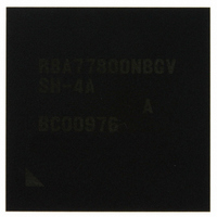
R8A77800ANBGAV Renesas Electronics America, R8A77800ANBGAV Datasheet - Page 50

R8A77800ANBGAV
Manufacturer Part Number
R8A77800ANBGAV
Description
IC SUPERH MPU ROMLESS 449-BGA
Manufacturer
Renesas Electronics America
Series
SuperH® SH7780r
Datasheet
1.R8A77800ANBGV.pdf
(1342 pages)
Specifications of R8A77800ANBGAV
Core Processor
SH-4A
Core Size
32-Bit
Speed
400MHz
Connectivity
Audio Codec, MMC, Serial Sound, SCI, SIO, SPI, SSI
Peripherals
DMA, POR, WDT
Number Of I /o
75
Program Memory Type
ROMless
Ram Size
16K x 8
Voltage - Supply (vcc/vdd)
1.15 V ~ 1.35 V
Oscillator Type
External
Operating Temperature
-20°C ~ 75°C
Package / Case
449-BGA
Lead Free Status / RoHS Status
Lead free / RoHS Compliant
Eeprom Size
-
Program Memory Size
-
Data Converters
-
Available stocks
Company
Part Number
Manufacturer
Quantity
Price
Company:
Part Number:
R8A77800ANBGAV
Manufacturer:
Renesas Electronics America
Quantity:
10 000
- Current page: 50 of 1342
- Download datasheet (7Mb)
Section 25 Audio Codec Interface (HAC)
Table 25.1
Table 25.2
Table 25.3
Table 25.4
Table 25.5
Section 26 Serial Sound Interface (SSI) Module
Table 26.1
Table 26.2
Table 26.3
Table 26.4
Table 26.5
Section 27 NAND Flash Memory Controller (FLCTL)
Table 27.1
Table 27.2
Table 27.3
Table 27.4
Table 27.5
Table 27.6
Section 28 General Purpose I/O (GPIO)
Table 28.1
Table 28.2
Table 28.3
Section 29 User Break Controller (UBC)
Table 29.1
Table 29.2
Table 29.3
Table 29.4
Section 30 User Debugging Interface (H-UDI)
Table 30.1
Table 30.2
Table 30.3
Table 30.4
Table 30.5
Table 30.6
Section 31 Electrical Characteristics
Table 31.1
Rev.1.00 Dec. 13, 2005 Page xlviii of l
Pin Configuration.................................................................................................. 956
Register Configuration.......................................................................................... 957
Register States of HAC in Each Processing Mode ............................................... 957
AC97 Transmit Frame Structure........................................................................... 973
AC97 Receive Frame Structure ............................................................................ 974
Pin Configuration.................................................................................................. 984
Register Configuration.......................................................................................... 985
Register States of SSI in Each Processing Mode .................................................. 985
Bus Formats of SSI Module.................................................................................. 998
Number of Padding Bits for Each Valid Configuration...................................... 1002
Pin Configuration................................................................................................ 1024
Register Configuration of FLCTL ...................................................................... 1025
Register States of FLCTL in Each Processing Mode.......................................... 1025
Status Read of NAND-Type Flash Memory....................................................... 1049
FLCTL Interrupt Requests.................................................................................. 1053
DMA Transfer Specifications ............................................................................. 1053
Multiplexed Pins Controlled by Port Control Registers ..................................... 1056
Register Configuration........................................................................................ 1060
Register States of GPIO in Each Processing Mode ............................................ 1062
Register Configuration........................................................................................ 1103
Register Status in Each Processing State ............................................................ 1104
Settings for Match Data Setting Register............................................................ 1116
Relation between Operand Sizes and Address Bits to be Compared .................. 1123
Pin Configuration................................................................................................ 1137
Commands Supported by Boundary-Scan TAP Controller ................................ 1139
Register Configuration (1) .................................................................................. 1140
Register Configuration (2) .................................................................................. 1140
Register Status in Each Processing State ............................................................ 1140
SDBSR Configuration ........................................................................................ 1143
Absolute Maximum Ratings ............................................................................... 1155
Related parts for R8A77800ANBGAV
Image
Part Number
Description
Manufacturer
Datasheet
Request
R

Part Number:
Description:
KIT STARTER FOR M16C/29
Manufacturer:
Renesas Electronics America
Datasheet:

Part Number:
Description:
KIT STARTER FOR R8C/2D
Manufacturer:
Renesas Electronics America
Datasheet:

Part Number:
Description:
R0K33062P STARTER KIT
Manufacturer:
Renesas Electronics America
Datasheet:

Part Number:
Description:
KIT STARTER FOR R8C/23 E8A
Manufacturer:
Renesas Electronics America
Datasheet:

Part Number:
Description:
KIT STARTER FOR R8C/25
Manufacturer:
Renesas Electronics America
Datasheet:

Part Number:
Description:
KIT STARTER H8S2456 SHARPE DSPLY
Manufacturer:
Renesas Electronics America
Datasheet:

Part Number:
Description:
KIT STARTER FOR R8C38C
Manufacturer:
Renesas Electronics America
Datasheet:

Part Number:
Description:
KIT STARTER FOR R8C35C
Manufacturer:
Renesas Electronics America
Datasheet:

Part Number:
Description:
KIT STARTER FOR R8CL3AC+LCD APPS
Manufacturer:
Renesas Electronics America
Datasheet:

Part Number:
Description:
KIT STARTER FOR RX610
Manufacturer:
Renesas Electronics America
Datasheet:

Part Number:
Description:
KIT STARTER FOR R32C/118
Manufacturer:
Renesas Electronics America
Datasheet:

Part Number:
Description:
KIT DEV RSK-R8C/26-29
Manufacturer:
Renesas Electronics America
Datasheet:

Part Number:
Description:
KIT STARTER FOR SH7124
Manufacturer:
Renesas Electronics America
Datasheet:

Part Number:
Description:
KIT STARTER FOR H8SX/1622
Manufacturer:
Renesas Electronics America
Datasheet:

Part Number:
Description:
KIT DEV FOR SH7203
Manufacturer:
Renesas Electronics America
Datasheet:


