R8A77800ANBGAV Renesas Electronics America, R8A77800ANBGAV Datasheet - Page 37
R8A77800ANBGAV
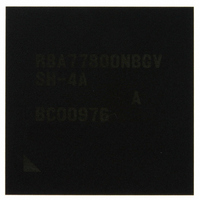
Manufacturer Part Number
R8A77800ANBGAV
Description
IC SUPERH MPU ROMLESS 449-BGA
Manufacturer
Renesas Electronics America
Series
SuperH® SH7780r
Datasheet
1.R8A77800ANBGV.pdf
(1342 pages)
Specifications of R8A77800ANBGAV
Core Processor
SH-4A
Core Size
32-Bit
Speed
400MHz
Connectivity
Audio Codec, MMC, Serial Sound, SCI, SIO, SPI, SSI
Peripherals
DMA, POR, WDT
Number Of I /o
75
Program Memory Type
ROMless
Ram Size
16K x 8
Voltage - Supply (vcc/vdd)
1.15 V ~ 1.35 V
Oscillator Type
External
Operating Temperature
-20°C ~ 75°C
Package / Case
449-BGA
Lead Free Status / RoHS Status
Lead free / RoHS Compliant
Eeprom Size
-
Program Memory Size
-
Data Converters
-
Available stocks
Company
Part Number
Manufacturer
Quantity
Price
Company:

Part Number:
R8A77800ANBGAV
Manufacturer:
Renesas Electronics America
Quantity:
10 000


Figure 19.5 CMT_CTRn Assert Timing (channel 0 and 1) ........................................................ 694
Figure 19.6 32-Bit Timer Mode: Output Compare (channel 1 and channel 0) ........................... 694
Figure 19.7 32-bit Timer Mode: Output Compare Operation Timing
Figure 19.8 32-bit Timer Mode: Output Compare Operation Timing
Figure 19.9 16-Bit Timer Mode: Input Capture (channel 1 and channel 0)................................ 697
Figure 19.10 16-Bit Timer Mode: Input Capture Operation Timing .......................................... 698
Figure 19.11 16-Bit Timer Mode: Output Compare
Figure 19.12 16-Bit Timer Mode: Output Compare Operation Timing ..................................... 700
Figure 19.13 Up-Counter Mode (channel 1 and channel 0)........................................................ 701
Figure 19.14 Up-counter Mode Operation Timing..................................................................... 701
Figure 19.15 Updown-Counter Mode (only channel 0).............................................................. 703
Figure 19.16 Updown-Counter Mode: Countdown Operation Timing (only channel 0)............ 703
Figure 19.17 Rotary Switch Operation Count-Up Timing.......................................................... 705
Figure 19.18 Rotary Switch Operation Count-Down Timing..................................................... 705
Section 20 Realtime Clock (RTC)
Figure 20.1 Block Diagram of RTC ........................................................................................... 708
Figure 20.2 Examples of Time Setting Procedures..................................................................... 727
Figure 20.3 Examples of Time Reading Procedures................................................................... 728
Figure 20.4 Example of Use of Alarm Function......................................................................... 729
Figure 20.5 Example of Crystal Oscillator Circuit Connection .................................................. 731
Figure 20.6 Interrupt Request Signal Generation Timing of Complex Sources ......................... 732
Section 21 Serial Communication Interface with FIFO (SCIF)
Figure 21.1 Block Diagram of SCIF........................................................................................... 735
Figure 21.2 SCIF0_RTS Pin (Only in Channel 0) ...................................................................... 736
Figure 21.3 SCIF0_CTS Pin (Only in Channel 0) ...................................................................... 736
Figure 21.4 SCIFn_SCK Pin (n = 0, 1)....................................................................................... 737
Figure 21.5 SCIFn_TXD Pin (n = 0, 1) ...................................................................................... 737
Figure 21.6 SCIFn_RXD Pin (n = 0, 1)...................................................................................... 738
Figure 21.7 Data Format in Asynchronous Communication
Figure 21.8 Sample SCIF Initialization Flowchart ..................................................................... 775
Figure 21.9 Sample Serial Transmission Flowchart ................................................................... 776
Figure 21.10 Sample SCIF Transmission Operation
Figure 21.11 Sample Operation Using Modem Control (SCIF0_CTS) (Only in Channel 0) ..... 778
Figure 21.12 Sample Serial Reception Flowchart (1)................................................................. 779
(Example with 8-Bit Data, Parity, and Two Stop Bits) ........................................... 772
(Example of High output in Active and Not Active by CMTCHnST).................... 695
(Example of High output in Active and Not Active by CMTFRT)......................... 695
(CMT_CTR pins are available for channel 1 and channel 0) ................................ 699
(Example with 8-Bit Data, Parity, One Stop Bit).................................................. 778
Rev.1.00 Dec. 13, 2005 Page xxxv of l
Related parts for R8A77800ANBGAV
Image
Part Number
Description
Manufacturer
Datasheet
Request
R

Part Number:
Description:
KIT STARTER FOR M16C/29
Manufacturer:
Renesas Electronics America
Datasheet:

Part Number:
Description:
KIT STARTER FOR R8C/2D
Manufacturer:
Renesas Electronics America
Datasheet:

Part Number:
Description:
R0K33062P STARTER KIT
Manufacturer:
Renesas Electronics America
Datasheet:

Part Number:
Description:
KIT STARTER FOR R8C/23 E8A
Manufacturer:
Renesas Electronics America
Datasheet:

Part Number:
Description:
KIT STARTER FOR R8C/25
Manufacturer:
Renesas Electronics America
Datasheet:

Part Number:
Description:
KIT STARTER H8S2456 SHARPE DSPLY
Manufacturer:
Renesas Electronics America
Datasheet:

Part Number:
Description:
KIT STARTER FOR R8C38C
Manufacturer:
Renesas Electronics America
Datasheet:

Part Number:
Description:
KIT STARTER FOR R8C35C
Manufacturer:
Renesas Electronics America
Datasheet:

Part Number:
Description:
KIT STARTER FOR R8CL3AC+LCD APPS
Manufacturer:
Renesas Electronics America
Datasheet:
Part Number:
Description:
KIT STARTER FOR RX610
Manufacturer:
Renesas Electronics America
Datasheet:

Part Number:
Description:
KIT STARTER FOR R32C/118
Manufacturer:
Renesas Electronics America
Datasheet:

Part Number:
Description:
KIT DEV RSK-R8C/26-29
Manufacturer:
Renesas Electronics America
Datasheet:

Part Number:
Description:
KIT STARTER FOR SH7124
Manufacturer:
Renesas Electronics America
Datasheet:

Part Number:
Description:
KIT STARTER FOR H8SX/1622
Manufacturer:
Renesas Electronics America
Datasheet:

Part Number:
Description:
KIT DEV FOR SH7203
Manufacturer:
Renesas Electronics America
Datasheet: