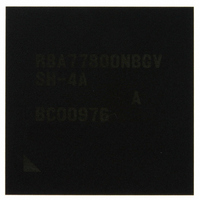
R8A77800ANBGAV Renesas Electronics America, R8A77800ANBGAV Datasheet - Page 474

R8A77800ANBGAV
Manufacturer Part Number
R8A77800ANBGAV
Description
IC SUPERH MPU ROMLESS 449-BGA
Manufacturer
Renesas Electronics America
Series
SuperH® SH7780r
Datasheet
1.R8A77800ANBGV.pdf
(1342 pages)
Specifications of R8A77800ANBGAV
Core Processor
SH-4A
Core Size
32-Bit
Speed
400MHz
Connectivity
Audio Codec, MMC, Serial Sound, SCI, SIO, SPI, SSI
Peripherals
DMA, POR, WDT
Number Of I /o
75
Program Memory Type
ROMless
Ram Size
16K x 8
Voltage - Supply (vcc/vdd)
1.15 V ~ 1.35 V
Oscillator Type
External
Operating Temperature
-20°C ~ 75°C
Package / Case
449-BGA
Lead Free Status / RoHS Status
Lead free / RoHS Compliant
Eeprom Size
-
Program Memory Size
-
Data Converters
-
Available stocks
Company
Part Number
Manufacturer
Quantity
Price
Company:
Part Number:
R8A77800ANBGAV
Manufacturer:
Renesas Electronics America
Quantity:
10 000
- Current page: 474 of 1342
- Download datasheet (7Mb)
Section 12 DDR-SDRAM Interface (DDRIF)
12.4.5
SDMR refers to the mode register and extended mode register of the DDR-SDRAM. Since the
SDMR is physically within the SDRAM rather than the DDRIF, reading the registers is invalid.
Only the address bits have any meaning for the DDR-SDRAM and any data included in the write
operation is ignored.
Writing to the SDMR proceeds when the signal output on pins connected to the DDR-SDRAM is
as shown in the table below.
Address bits 12 to 3 correspond to external pins MA9 to MA0, address bits 14 and 13 to external
pins BA1 and BA0, and address bits 18 to 15 to external pins MA13 to MA10. These bits contain
the values for the mode registers.
Rev.1.00 Dec. 13, 2005 Page 422 of 1286
REJ09B0158-0100
Bit
63 to 12
11 to 8
7 to 0
SDRAM Mode Register (SDMR)
Bit Name
SPLIT
Initial
Value
All 0
0001
All 0
R/W
R
R/W
R
Description
Reserved
These bits are always read as 0. The write value
should always be 0.
DDR-SDRAM Memory Configuration
These bits specify the row/column configuration of the
DDR-SDRAM.
0001: 12 × 9 (= product with 8 M × 16 bits)
0011: 13 × 9 (= product with 16 M × 16 bits)
0100: 13 × 10 (= product with 32 M × 16 bits)
0110: 14 × 10 (= product with 64 M × 16 bits)
Other than above: Setting prohibited
The relationship between the SPLIT bits and numbers
of rows and columns is shown in section 12.5.6,
Address Multiplexing.
Reserved
These bits are always read as 0. The write value
should always be 0.
Related parts for R8A77800ANBGAV
Image
Part Number
Description
Manufacturer
Datasheet
Request
R

Part Number:
Description:
KIT STARTER FOR M16C/29
Manufacturer:
Renesas Electronics America
Datasheet:

Part Number:
Description:
KIT STARTER FOR R8C/2D
Manufacturer:
Renesas Electronics America
Datasheet:

Part Number:
Description:
R0K33062P STARTER KIT
Manufacturer:
Renesas Electronics America
Datasheet:

Part Number:
Description:
KIT STARTER FOR R8C/23 E8A
Manufacturer:
Renesas Electronics America
Datasheet:

Part Number:
Description:
KIT STARTER FOR R8C/25
Manufacturer:
Renesas Electronics America
Datasheet:

Part Number:
Description:
KIT STARTER H8S2456 SHARPE DSPLY
Manufacturer:
Renesas Electronics America
Datasheet:

Part Number:
Description:
KIT STARTER FOR R8C38C
Manufacturer:
Renesas Electronics America
Datasheet:

Part Number:
Description:
KIT STARTER FOR R8C35C
Manufacturer:
Renesas Electronics America
Datasheet:

Part Number:
Description:
KIT STARTER FOR R8CL3AC+LCD APPS
Manufacturer:
Renesas Electronics America
Datasheet:

Part Number:
Description:
KIT STARTER FOR RX610
Manufacturer:
Renesas Electronics America
Datasheet:

Part Number:
Description:
KIT STARTER FOR R32C/118
Manufacturer:
Renesas Electronics America
Datasheet:

Part Number:
Description:
KIT DEV RSK-R8C/26-29
Manufacturer:
Renesas Electronics America
Datasheet:

Part Number:
Description:
KIT STARTER FOR SH7124
Manufacturer:
Renesas Electronics America
Datasheet:

Part Number:
Description:
KIT STARTER FOR H8SX/1622
Manufacturer:
Renesas Electronics America
Datasheet:

Part Number:
Description:
KIT DEV FOR SH7203
Manufacturer:
Renesas Electronics America
Datasheet:


