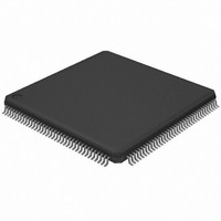
AT32UC3A364-ALUT Atmel, AT32UC3A364-ALUT Datasheet - Page 564

AT32UC3A364-ALUT
Manufacturer Part Number
AT32UC3A364-ALUT
Description
IC MCU 64KB FLASH 144LQFP
Manufacturer
Atmel
Series
AVR®32 UC3r
Specifications of AT32UC3A364-ALUT
Core Processor
AVR
Core Size
32-Bit
Speed
66MHz
Connectivity
EBI/EMI, I²C, IrDA, MMC, SPI, SSC, UART/USART, USB OTG
Peripherals
Brown-out Detect/Reset, DMA, POR, WDT
Number Of I /o
110
Program Memory Size
64KB (64K x 8)
Program Memory Type
FLASH
Ram Size
128K x 8
Voltage - Supply (vcc/vdd)
1.65 V ~ 1.95 V
Data Converters
A/D 8x10b
Oscillator Type
Internal
Operating Temperature
-40°C ~ 85°C
Package / Case
144-LQFP
Processor Series
AT32UC3x
Core
AVR32
Data Bus Width
32 bit
Data Ram Size
96 KB
Interface Type
IrDA/SCI/SCIF/UDI
Maximum Clock Frequency
66 MHz
Number Of Timers
3
Operating Supply Voltage
3 V to 3.6 V
Maximum Operating Temperature
+ 85 C
Mounting Style
SMD/SMT
3rd Party Development Tools
EWAVR32, EWAVR32-BL, KSK-EVK1100-PL
Development Tools By Supplier
ATAVRDRAGON, ATSTK500, ATSTK600, ATAVRISP2, ATAVRONEKIT, ATEXTWIFI, ATEVK1104
Minimum Operating Temperature
- 40 C
Controller Family/series
AT32UC3A
No. Of I/o's
110
Ram Memory Size
64KB
Cpu Speed
66MHz
No. Of Timers
2
Rohs Compliant
Yes
For Use With
ATEVK1104 - KIT DEV/EVAL FOR AVR32 AT32UC3AATAVRONEKIT - KIT AVR/AVR32 DEBUGGER/PROGRMMRATEVK1100 - KIT DEV/EVAL FOR AVR32 AT32UC3A
Lead Free Status / RoHS Status
Lead free / RoHS Compliant
Eeprom Size
-
Lead Free Status / Rohs Status
Lead free / RoHS Compliant
Available stocks
Company
Part Number
Manufacturer
Quantity
Price
- Current page: 564 of 1014
- Download datasheet (16Mb)
Figure 25-22. Timeguard Operations
25.6.3.11
32072C–AVR32–2010/03
Baud Rate
TXEMPTY
TXRDY
Clock
Write
THR
TXD
Receiver Time-out
Start
Bit
D0
D1
Table 25-8
in relation to the function of the Baud Rate.
Table 25-8.
The Receiver Time-out provides support in handling variable-length frames. This feature detects
an idle condition on the RXD line. When a time-out is detected, the bit TIMEOUT in the Channel
Status Register (CSR) rises and can generate an interrupt, thus indicating to the driver an end of
frame.
The time-out delay period (during which the receiver waits for a new character) is programmed
in the TO field of the Receiver Time-out Register (RTOR). If the TO field is programmed at 0, the
Receiver Time-out is disabled and no time-out is detected. The TIMEOUT bit in CSR remains at
0. Otherwise, the receiver loads a counter with the value programmed in TO. This counter is
decremented at each bit period and reloaded each time a new character is received. If the coun-
ter reaches 0, the TIMEOUT bit in the Status Register rises. Then, the user can either:
D2
• Stop the counter clock until a new character is received. This is performed by writing the
Control Register (CR) with the STTTO (Start Time-out) bit at 1. In this case, the idle state on
RXD before a new character is received will not provide a time-out. This prevents having to
D3
D4
D5
Baud Rate
indicates the maximum length of a timeguard period that the transmitter can handle
115200
Bit/sec
14400
19200
28800
33400
56000
57600
1 200
9 600
D6
Maximum Timeguard Length Depending on Baud Rate
D7
Parity
Bit
Stop
Bit
TG = 4
Start
Bit
D0
Bit time
69.4
52.1
34.7
29.9
17.9
17.4
D1
833
104
8.7
µs
D2
D3
D4
D5
D6
D7
AT32UC3A3/A4
Parity
Bit
Stop
Bit
Timeguard
212.50
17.71
13.28
26.56
8.85
7.63
4.55
4.43
2.21
ms
TG = 4
564
Related parts for AT32UC3A364-ALUT
Image
Part Number
Description
Manufacturer
Datasheet
Request
R

Part Number:
Description:
KIT DEV/EVAL FOR AT32UC3A3
Manufacturer:
Atmel
Datasheet:

Part Number:
Description:
DEV KIT FOR AVR/AVR32
Manufacturer:
Atmel
Datasheet:

Part Number:
Description:
INTERVAL AND WIPE/WASH WIPER CONTROL IC WITH DELAY
Manufacturer:
ATMEL Corporation
Datasheet:

Part Number:
Description:
Low-Voltage Voice-Switched IC for Hands-Free Operation
Manufacturer:
ATMEL Corporation
Datasheet:

Part Number:
Description:
MONOLITHIC INTEGRATED FEATUREPHONE CIRCUIT
Manufacturer:
ATMEL Corporation
Datasheet:

Part Number:
Description:
AM-FM Receiver IC U4255BM-M
Manufacturer:
ATMEL Corporation
Datasheet:

Part Number:
Description:
Monolithic Integrated Feature Phone Circuit
Manufacturer:
ATMEL Corporation
Datasheet:

Part Number:
Description:
Multistandard Video-IF and Quasi Parallel Sound Processing
Manufacturer:
ATMEL Corporation
Datasheet:

Part Number:
Description:
High-performance EE PLD
Manufacturer:
ATMEL Corporation
Datasheet:

Part Number:
Description:
8-bit Flash Microcontroller
Manufacturer:
ATMEL Corporation
Datasheet:

Part Number:
Description:
2-Wire Serial EEPROM
Manufacturer:
ATMEL Corporation
Datasheet:


