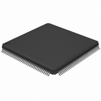
AT32UC3A364-ALUT Atmel, AT32UC3A364-ALUT Datasheet - Page 475

AT32UC3A364-ALUT
Manufacturer Part Number
AT32UC3A364-ALUT
Description
IC MCU 64KB FLASH 144LQFP
Manufacturer
Atmel
Series
AVR®32 UC3r
Specifications of AT32UC3A364-ALUT
Core Processor
AVR
Core Size
32-Bit
Speed
66MHz
Connectivity
EBI/EMI, I²C, IrDA, MMC, SPI, SSC, UART/USART, USB OTG
Peripherals
Brown-out Detect/Reset, DMA, POR, WDT
Number Of I /o
110
Program Memory Size
64KB (64K x 8)
Program Memory Type
FLASH
Ram Size
128K x 8
Voltage - Supply (vcc/vdd)
1.65 V ~ 1.95 V
Data Converters
A/D 8x10b
Oscillator Type
Internal
Operating Temperature
-40°C ~ 85°C
Package / Case
144-LQFP
Processor Series
AT32UC3x
Core
AVR32
Data Bus Width
32 bit
Data Ram Size
96 KB
Interface Type
IrDA/SCI/SCIF/UDI
Maximum Clock Frequency
66 MHz
Number Of Timers
3
Operating Supply Voltage
3 V to 3.6 V
Maximum Operating Temperature
+ 85 C
Mounting Style
SMD/SMT
3rd Party Development Tools
EWAVR32, EWAVR32-BL, KSK-EVK1100-PL
Development Tools By Supplier
ATAVRDRAGON, ATSTK500, ATSTK600, ATAVRISP2, ATAVRONEKIT, ATEXTWIFI, ATEVK1104
Minimum Operating Temperature
- 40 C
Controller Family/series
AT32UC3A
No. Of I/o's
110
Ram Memory Size
64KB
Cpu Speed
66MHz
No. Of Timers
2
Rohs Compliant
Yes
For Use With
ATEVK1104 - KIT DEV/EVAL FOR AVR32 AT32UC3AATAVRONEKIT - KIT AVR/AVR32 DEBUGGER/PROGRMMRATEVK1100 - KIT DEV/EVAL FOR AVR32 AT32UC3A
Lead Free Status / RoHS Status
Lead free / RoHS Compliant
Eeprom Size
-
Lead Free Status / Rohs Status
Lead free / RoHS Compliant
Available stocks
Company
Part Number
Manufacturer
Quantity
Price
- Current page: 475 of 1014
- Download datasheet (16Mb)
23.8.3
32072C–AVR32–2010/03
Master Transmitter Mode
The interrupt system can be set up to give interrupt request on specific events or error condi-
tions, for example when the transfer is complete or if arbitration is lost.
The controller will refuse to start a new transfer while ANAK, DNAK or ARBLST is set in the Sta-
tus Register (SR). This is necessary to avoid a race when the software issues a continuation of
the current transfer at the same time as one of these errors happen. Also, if ANAK or DNAK
occur, a STOP condition is sent automatically. The programmer will have to restart the transmis-
sion by clearing the errors bit in SR after resolving the cause for the NACK.
After a data or address NACK from the slave, a STOP will be transmitted automatically. Note
that the VALID bit in CMDR is NOT cleared in this case. If this transfer is to be discarded, the
VALID bit can be cleared manually allowing any command in NCMDR to be copied into CMDR.
When a data or address NACK is returned by the slave while the master is transmitting, it is pos-
sible that new data has already been written to the THR register. This data will be transferred out
as the first data byte of the next transfer. If this behavior is to be avoided, the safest approach is
to perform a software reset of the TWIM.
A START condition is transmitted and master transmitter mode is initiated when the bus is free
and CMDR has been written with START=1 and READ=0. START and SADR+W will then be
transmitted. During the address acknowledge clock pulse (9th pulse), the master releases the
data line (HIGH), enabling the slave to pull it down in order to acknowledge the address. The
master polls the data line during this clock pulse and sets the Address Not Acknowledged bit
(ANAK) in the Status Register if no slave acknowledges the address.
After the address phase, the following is repeated:
while (NBYTES>0)
Programming CMDR with START=STOP=1 and NBYTES=0 will generate a transmission with
no data bytes, ie START, SADR+W, STOP.
TWI transfers require the slave to acknowledge each received data byte. During the acknowl-
edge clock pulse (9th pulse), the master releases the data line (HIGH), enabling the slave to pull
it down in order to generate the acknowledge. The master polls the data line during this clock
pulse and sets the Data Acknowledge bit (DNACK) in the Status Register if the slave does not
acknowledge the data byte. As with the other status bits, an interrupt can be generated if
enabled in the Interrupt Enable Register (TWIM_IER).
TXRDY is used as Transmit Ready for the Peripheral DMA Controller transmit channel.
1. Before any transfers can be performed, bus timings must be configured by program-
2. If a DMA controller is to be used for the transfers, it must be set up.
3. CMDR or NCMDR must be programmed with a value describing the transfer to be
1. Wait until THR contains a valid data byte, stretching low period of TWCK. SR.TXRDY
2. Transmit this data byte
3. Decrement NBYTES
4. If (NBYTES==0) and STOP=1, transmit STOP condition
ming the Clock Waveform Generator Register (CWGR). If operating in SMBus mode,
the SMBus Timing Register (SMBTR) register must also be configured.
performed.
indicates the state of THR. Software or a DMA controller must write the data byte to
THR.
AT32UC3A3/A4
475
Related parts for AT32UC3A364-ALUT
Image
Part Number
Description
Manufacturer
Datasheet
Request
R

Part Number:
Description:
KIT DEV/EVAL FOR AT32UC3A3
Manufacturer:
Atmel
Datasheet:

Part Number:
Description:
DEV KIT FOR AVR/AVR32
Manufacturer:
Atmel
Datasheet:

Part Number:
Description:
INTERVAL AND WIPE/WASH WIPER CONTROL IC WITH DELAY
Manufacturer:
ATMEL Corporation
Datasheet:

Part Number:
Description:
Low-Voltage Voice-Switched IC for Hands-Free Operation
Manufacturer:
ATMEL Corporation
Datasheet:

Part Number:
Description:
MONOLITHIC INTEGRATED FEATUREPHONE CIRCUIT
Manufacturer:
ATMEL Corporation
Datasheet:

Part Number:
Description:
AM-FM Receiver IC U4255BM-M
Manufacturer:
ATMEL Corporation
Datasheet:

Part Number:
Description:
Monolithic Integrated Feature Phone Circuit
Manufacturer:
ATMEL Corporation
Datasheet:

Part Number:
Description:
Multistandard Video-IF and Quasi Parallel Sound Processing
Manufacturer:
ATMEL Corporation
Datasheet:

Part Number:
Description:
High-performance EE PLD
Manufacturer:
ATMEL Corporation
Datasheet:

Part Number:
Description:
8-bit Flash Microcontroller
Manufacturer:
ATMEL Corporation
Datasheet:

Part Number:
Description:
2-Wire Serial EEPROM
Manufacturer:
ATMEL Corporation
Datasheet:


