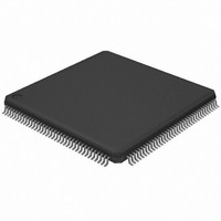
AT32UC3A364-ALUT Atmel, AT32UC3A364-ALUT Datasheet - Page 482

AT32UC3A364-ALUT
Manufacturer Part Number
AT32UC3A364-ALUT
Description
IC MCU 64KB FLASH 144LQFP
Manufacturer
Atmel
Series
AVR®32 UC3r
Specifications of AT32UC3A364-ALUT
Core Processor
AVR
Core Size
32-Bit
Speed
66MHz
Connectivity
EBI/EMI, I²C, IrDA, MMC, SPI, SSC, UART/USART, USB OTG
Peripherals
Brown-out Detect/Reset, DMA, POR, WDT
Number Of I /o
110
Program Memory Size
64KB (64K x 8)
Program Memory Type
FLASH
Ram Size
128K x 8
Voltage - Supply (vcc/vdd)
1.65 V ~ 1.95 V
Data Converters
A/D 8x10b
Oscillator Type
Internal
Operating Temperature
-40°C ~ 85°C
Package / Case
144-LQFP
Processor Series
AT32UC3x
Core
AVR32
Data Bus Width
32 bit
Data Ram Size
96 KB
Interface Type
IrDA/SCI/SCIF/UDI
Maximum Clock Frequency
66 MHz
Number Of Timers
3
Operating Supply Voltage
3 V to 3.6 V
Maximum Operating Temperature
+ 85 C
Mounting Style
SMD/SMT
3rd Party Development Tools
EWAVR32, EWAVR32-BL, KSK-EVK1100-PL
Development Tools By Supplier
ATAVRDRAGON, ATSTK500, ATSTK600, ATAVRISP2, ATAVRONEKIT, ATEXTWIFI, ATEVK1104
Minimum Operating Temperature
- 40 C
Controller Family/series
AT32UC3A
No. Of I/o's
110
Ram Memory Size
64KB
Cpu Speed
66MHz
No. Of Timers
2
Rohs Compliant
Yes
For Use With
ATEVK1104 - KIT DEV/EVAL FOR AVR32 AT32UC3AATAVRONEKIT - KIT AVR/AVR32 DEBUGGER/PROGRMMRATEVK1100 - KIT DEV/EVAL FOR AVR32 AT32UC3A
Lead Free Status / RoHS Status
Lead free / RoHS Compliant
Eeprom Size
-
Lead Free Status / Rohs Status
Lead free / RoHS Compliant
Available stocks
Company
Part Number
Manufacturer
Quantity
Price
- Current page: 482 of 1014
- Download datasheet (16Mb)
Figure 23-15. A Read Transfer with 10-bit Addressing
23.8.9
23.8.9.1
32072C–AVR32–2010/03
S
1
SLAVE ADDRESS
1
SMBus Mode
1
1st 7 bits
Packet Error Checking
1
0
X
X
RW A1
SMBus mode is enabled and disabled by the SMEN and SMDIS bits in CR. SMBus mode oper-
ation is similar to I²C operation with the following exceptions:
Each SMBus transfer can optionally end with a CRC byte, called the PEC byte. Writing
CMDR.PECEN to one enables automatic PEC handling in the current transfer. Transfers with
and without PEC can freely be intermixed in the same system, since some slaves may not sup-
port PEC. The PEC LFSR is always updated on every bit transmitted or received, so that PEC
handling on combined transfers will be correct.
In master transmitter mode, the master calculates a PEC value and transmits it to the slave after
all data bytes have been transmitted. Upon reception of this PEC byte, the slave will compare it
to the PEC value it has computed itself. If the values match, the data was received correctly, and
the slave will return an ACK to the master. If the PEC values differ, data was corrupted, and the
slave will return a NACK value. The DNAK bit in SR reflects the state of the last received
ACK/NACK value. Some slaves may not be able to check the received PEC in time to return a
NACK if an error occurred. In this case, the slave should always return an ACK after the PEC
byte, and some other mechanism must be implemented to verify that the transmission was
received correctly.
In master receiver mode, the slave calculates a PEC value and transmits it to the master after all
data bytes have been transmitted. Upon reception of this PEC byte, the master will compare it to
the PEC value it has computed itself. If the values match, the data was received correctly. If the
PEC values differ, data was corrupted, and the PECERR bit in SR is set. In master receiver
mode, the PEC byte is always followed by a NACK transmitted by the master, since it is the last
byte in the transfer.
The PEC byte is automatically inserted in a master transmitter transmission if PEC is enabled
when NBYTES reaches zero. The PEC byte is identified in a master receiver transmission if
PEC is enabled when NBYTES reaches zero. NBYTES must therefore be set to the total num-
ber of data bytes in the transmission, including the PEC byte.
0
1. Program CMDR with TENBIT=1, REPSAME=0, READ=0, START=1, STOP=0,
2. Program NCMDR with TENBIT=1, REPSAME=1, READ=1, START=1, STOP=1 and
• Only 7-bit addressing can be used.
• The SMBus standard describes a set of timeout values to ensure progress and throughput on
• Transmissions can optionally include a CRC byte, called Packet Error Check (PEC).
• A dedicated bus line, SMBALERT, allows a slave to get a master’s attention.
• A set of addresses have been reserved for protocol handling, such as Alert Response
the bus. These timeout values must be programmed into SMBTR.
Address (ARA) and Host Header (HH) Address.
NBYTES=0 and the desired address.
the desired address and NBYTES value.
SLAVE ADDRESS
2nd byte
A2
Sr
1
SLAVE ADDRESS
1
1
1st 7 bits
1
0
X
X
RW A3
1
DATA
AT32UC3A3/A4
A
DATA
A
P
482
Related parts for AT32UC3A364-ALUT
Image
Part Number
Description
Manufacturer
Datasheet
Request
R

Part Number:
Description:
KIT DEV/EVAL FOR AT32UC3A3
Manufacturer:
Atmel
Datasheet:

Part Number:
Description:
DEV KIT FOR AVR/AVR32
Manufacturer:
Atmel
Datasheet:

Part Number:
Description:
INTERVAL AND WIPE/WASH WIPER CONTROL IC WITH DELAY
Manufacturer:
ATMEL Corporation
Datasheet:

Part Number:
Description:
Low-Voltage Voice-Switched IC for Hands-Free Operation
Manufacturer:
ATMEL Corporation
Datasheet:

Part Number:
Description:
MONOLITHIC INTEGRATED FEATUREPHONE CIRCUIT
Manufacturer:
ATMEL Corporation
Datasheet:

Part Number:
Description:
AM-FM Receiver IC U4255BM-M
Manufacturer:
ATMEL Corporation
Datasheet:

Part Number:
Description:
Monolithic Integrated Feature Phone Circuit
Manufacturer:
ATMEL Corporation
Datasheet:

Part Number:
Description:
Multistandard Video-IF and Quasi Parallel Sound Processing
Manufacturer:
ATMEL Corporation
Datasheet:

Part Number:
Description:
High-performance EE PLD
Manufacturer:
ATMEL Corporation
Datasheet:

Part Number:
Description:
8-bit Flash Microcontroller
Manufacturer:
ATMEL Corporation
Datasheet:

Part Number:
Description:
2-Wire Serial EEPROM
Manufacturer:
ATMEL Corporation
Datasheet:


