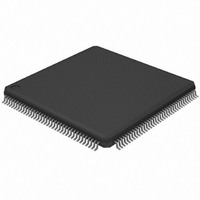
AT32UC3A364-ALUT Atmel, AT32UC3A364-ALUT Datasheet - Page 320

AT32UC3A364-ALUT
Manufacturer Part Number
AT32UC3A364-ALUT
Description
IC MCU 64KB FLASH 144LQFP
Manufacturer
Atmel
Series
AVR®32 UC3r
Specifications of AT32UC3A364-ALUT
Core Processor
AVR
Core Size
32-Bit
Speed
66MHz
Connectivity
EBI/EMI, I²C, IrDA, MMC, SPI, SSC, UART/USART, USB OTG
Peripherals
Brown-out Detect/Reset, DMA, POR, WDT
Number Of I /o
110
Program Memory Size
64KB (64K x 8)
Program Memory Type
FLASH
Ram Size
128K x 8
Voltage - Supply (vcc/vdd)
1.65 V ~ 1.95 V
Data Converters
A/D 8x10b
Oscillator Type
Internal
Operating Temperature
-40°C ~ 85°C
Package / Case
144-LQFP
Processor Series
AT32UC3x
Core
AVR32
Data Bus Width
32 bit
Data Ram Size
96 KB
Interface Type
IrDA/SCI/SCIF/UDI
Maximum Clock Frequency
66 MHz
Number Of Timers
3
Operating Supply Voltage
3 V to 3.6 V
Maximum Operating Temperature
+ 85 C
Mounting Style
SMD/SMT
3rd Party Development Tools
EWAVR32, EWAVR32-BL, KSK-EVK1100-PL
Development Tools By Supplier
ATAVRDRAGON, ATSTK500, ATSTK600, ATAVRISP2, ATAVRONEKIT, ATEXTWIFI, ATEVK1104
Minimum Operating Temperature
- 40 C
Controller Family/series
AT32UC3A
No. Of I/o's
110
Ram Memory Size
64KB
Cpu Speed
66MHz
No. Of Timers
2
Rohs Compliant
Yes
For Use With
ATEVK1104 - KIT DEV/EVAL FOR AVR32 AT32UC3AATAVRONEKIT - KIT AVR/AVR32 DEBUGGER/PROGRMMRATEVK1100 - KIT DEV/EVAL FOR AVR32 AT32UC3A
Lead Free Status / RoHS Status
Lead free / RoHS Compliant
Eeprom Size
-
Lead Free Status / Rohs Status
Lead free / RoHS Compliant
Available stocks
Company
Part Number
Manufacturer
Quantity
Price
- Current page: 320 of 1014
- Download datasheet (16Mb)
19.6
19.7
19.8
32072C–AVR32–2010/03
Arbitration for HSB Master Interface
Memory Peripherals
Handshaking Interface
Each DMACA channel has two request lines that request ownership of a particular master bus
interface: channel source and channel destination request lines.
Source and destination arbitrate separately for the bus. Once a source/destination state
machine gains ownership of the master bus interface and the master bus interface has owner-
ship of the HSB bus, then HSB transfers can proceed between the peripheral and the DMACA.
An arbitration scheme decides which of the request lines (2 * DMAH_NUM_CHANNELS) is
granted the particular master bus interface. Each channel has a programmable priority. A
request for the master bus interface can be made at any time, but is granted only after the cur-
rent HSB transfer (burst or single) has completed. Therefore, if the master interface is
transferring data for a lower priority channel and a higher priority channel requests service, then
the master interface will complete the current burst for the lower priority channel before switch-
ing to transfer data for the higher priority channel.
If only one request line is active at the highest priority level, then the request with the highest pri-
ority wins ownership of the HSB master bus interface; it is not necessary for the priority levels to
be unique.
If more than one request is active at the highest requesting priority, then these competing
requests proceed to a second tier of arbitration:
If equal priority requests occur, then the lower-numbered channel is granted.
In other words, if a peripheral request attached to Channel 7 and a peripheral request attached
to Channel 8 have the same priority, then the peripheral attached to Channel 7 is granted first.
Figure 19-3 on page 316
eral. There is no handshaking interface with the DMACA, and therefore the memory peripheral
can never be a flow controller. Once the channel is enabled, the transfer proceeds immediately
without waiting for a transaction request. The alternative to not having a transaction-level hand-
shaking interface is to allow the DMACA to attempt System Bus transfers to the peripheral once
the channel is enabled. If the peripheral slave cannot accept these System Bus transfers, it
inserts wait states onto the bus until it is ready; it is not recommended that more than 16 wait
states be inserted onto the bus. By using the handshaking interface, the peripheral can signal to
the DMACA that it is ready to transmit/receive data, and then the DMACA can access the
peripheral without the peripheral inserting wait states onto the bus.
Handshaking interfaces are used at the transaction level to control the flow of single or burst
transactions. The operation of the handshaking interface is different and depends on whether
the peripheral or the DMACA is the flow controller.
The peripheral uses the handshaking interface to indicate to the DMACA that it is ready to trans-
fer/accept data over the System Bus. A non-memory peripheral can request a DMA transfer
through the DMACA using one of two handshaking interfaces:
• Hardware handshaking
• Software handshaking
shows the DMA transfer hierarchy of the DMACA for a memory periph-
AT32UC3A3/A4
320
Related parts for AT32UC3A364-ALUT
Image
Part Number
Description
Manufacturer
Datasheet
Request
R

Part Number:
Description:
KIT DEV/EVAL FOR AT32UC3A3
Manufacturer:
Atmel
Datasheet:

Part Number:
Description:
DEV KIT FOR AVR/AVR32
Manufacturer:
Atmel
Datasheet:

Part Number:
Description:
INTERVAL AND WIPE/WASH WIPER CONTROL IC WITH DELAY
Manufacturer:
ATMEL Corporation
Datasheet:

Part Number:
Description:
Low-Voltage Voice-Switched IC for Hands-Free Operation
Manufacturer:
ATMEL Corporation
Datasheet:

Part Number:
Description:
MONOLITHIC INTEGRATED FEATUREPHONE CIRCUIT
Manufacturer:
ATMEL Corporation
Datasheet:

Part Number:
Description:
AM-FM Receiver IC U4255BM-M
Manufacturer:
ATMEL Corporation
Datasheet:

Part Number:
Description:
Monolithic Integrated Feature Phone Circuit
Manufacturer:
ATMEL Corporation
Datasheet:

Part Number:
Description:
Multistandard Video-IF and Quasi Parallel Sound Processing
Manufacturer:
ATMEL Corporation
Datasheet:

Part Number:
Description:
High-performance EE PLD
Manufacturer:
ATMEL Corporation
Datasheet:

Part Number:
Description:
8-bit Flash Microcontroller
Manufacturer:
ATMEL Corporation
Datasheet:

Part Number:
Description:
2-Wire Serial EEPROM
Manufacturer:
ATMEL Corporation
Datasheet:


