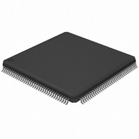
AT32UC3A364-ALUT Atmel, AT32UC3A364-ALUT Datasheet - Page 474

AT32UC3A364-ALUT
Manufacturer Part Number
AT32UC3A364-ALUT
Description
IC MCU 64KB FLASH 144LQFP
Manufacturer
Atmel
Series
AVR®32 UC3r
Specifications of AT32UC3A364-ALUT
Core Processor
AVR
Core Size
32-Bit
Speed
66MHz
Connectivity
EBI/EMI, I²C, IrDA, MMC, SPI, SSC, UART/USART, USB OTG
Peripherals
Brown-out Detect/Reset, DMA, POR, WDT
Number Of I /o
110
Program Memory Size
64KB (64K x 8)
Program Memory Type
FLASH
Ram Size
128K x 8
Voltage - Supply (vcc/vdd)
1.65 V ~ 1.95 V
Data Converters
A/D 8x10b
Oscillator Type
Internal
Operating Temperature
-40°C ~ 85°C
Package / Case
144-LQFP
Processor Series
AT32UC3x
Core
AVR32
Data Bus Width
32 bit
Data Ram Size
96 KB
Interface Type
IrDA/SCI/SCIF/UDI
Maximum Clock Frequency
66 MHz
Number Of Timers
3
Operating Supply Voltage
3 V to 3.6 V
Maximum Operating Temperature
+ 85 C
Mounting Style
SMD/SMT
3rd Party Development Tools
EWAVR32, EWAVR32-BL, KSK-EVK1100-PL
Development Tools By Supplier
ATAVRDRAGON, ATSTK500, ATSTK600, ATAVRISP2, ATAVRONEKIT, ATEXTWIFI, ATEVK1104
Minimum Operating Temperature
- 40 C
Controller Family/series
AT32UC3A
No. Of I/o's
110
Ram Memory Size
64KB
Cpu Speed
66MHz
No. Of Timers
2
Rohs Compliant
Yes
For Use With
ATEVK1104 - KIT DEV/EVAL FOR AVR32 AT32UC3AATAVRONEKIT - KIT AVR/AVR32 DEBUGGER/PROGRMMRATEVK1100 - KIT DEV/EVAL FOR AVR32 AT32UC3A
Lead Free Status / RoHS Status
Lead free / RoHS Compliant
Eeprom Size
-
Lead Free Status / Rohs Status
Lead free / RoHS Compliant
Available stocks
Company
Part Number
Manufacturer
Quantity
Price
- Current page: 474 of 1014
- Download datasheet (16Mb)
23.8.2.1
23.8.2.2
32072C–AVR32–2010/03
Clock Generation
Setting up and Performing a Transfer
The Clock Waveform Generator Register (CWGR) is used to control the waveform of the TWCK
clock. CWGR must be programmed so that the desired TWI bus timings are generated. CWGR
describes bus timings as a function of cycles of a prescaled clock. The clock prescaling can be
selected through the EXP field in CWGR.
CWGR has the following fields:
LOW: Prescaled clock cycles in clock low count. Used to time T
HIGH: Prescaled clock cycles in clock high count. Used to time T
STASTO: Prescaled clock cycles in clock high count. Used to time T
DATA: Prescaled clock cycles for data setup and hold count. Used to time T
EXP: Specifies the clock prescaler setting.
Note that the total clock low time generated is the sum of T
Any slave or other bus master taking part in the transfer may extend the TWCK low period at any
time.
The TWIM hardware monitors the state of the TWCK line as required by the I²C specification.
The clock generation counters are started when a high/low level is detected on the TWCK line,
not when the TWIM hardware releases/drives the TWCK line. This means that the CWGR set-
tings alone do not determine the TWCK frequency. The CWGR settings determine the clock low
time and the clock high time, but the TWCK rise and fall times are determined by the external cir-
cuitry (capacitive load, etc.).
Figure 23-5. Bus Timing Diagram
Operation of TWIM is mainly controlled by the Control Register (CR) and the Command Register
(CMDR). The following list presents the main steps in a typical communication:
f
prescaled
S
=
t
t LOW
------------------------- -
2
HD:STA
(
EXP
f
clkpb
+ )
1
t
)
SU:DAT
t HIGH
t
HD:DAT
t LOW
t
t
SU:DAT
SU:STA
HD_DAT
Sr
LOW
HIGH
+ T
AT32UC3A3/A4
. and T
HD_STA
.
SU_DAT
BUF
, T
HD_DAT
+ T
t
SU_STA
.
SU:STO
LOW
, T
.
, T
SU_DAT
SU_STO
P
.
474
.
Related parts for AT32UC3A364-ALUT
Image
Part Number
Description
Manufacturer
Datasheet
Request
R

Part Number:
Description:
KIT DEV/EVAL FOR AT32UC3A3
Manufacturer:
Atmel
Datasheet:

Part Number:
Description:
DEV KIT FOR AVR/AVR32
Manufacturer:
Atmel
Datasheet:

Part Number:
Description:
INTERVAL AND WIPE/WASH WIPER CONTROL IC WITH DELAY
Manufacturer:
ATMEL Corporation
Datasheet:

Part Number:
Description:
Low-Voltage Voice-Switched IC for Hands-Free Operation
Manufacturer:
ATMEL Corporation
Datasheet:

Part Number:
Description:
MONOLITHIC INTEGRATED FEATUREPHONE CIRCUIT
Manufacturer:
ATMEL Corporation
Datasheet:

Part Number:
Description:
AM-FM Receiver IC U4255BM-M
Manufacturer:
ATMEL Corporation
Datasheet:

Part Number:
Description:
Monolithic Integrated Feature Phone Circuit
Manufacturer:
ATMEL Corporation
Datasheet:

Part Number:
Description:
Multistandard Video-IF and Quasi Parallel Sound Processing
Manufacturer:
ATMEL Corporation
Datasheet:

Part Number:
Description:
High-performance EE PLD
Manufacturer:
ATMEL Corporation
Datasheet:

Part Number:
Description:
8-bit Flash Microcontroller
Manufacturer:
ATMEL Corporation
Datasheet:

Part Number:
Description:
2-Wire Serial EEPROM
Manufacturer:
ATMEL Corporation
Datasheet:


