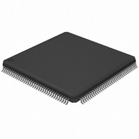
AT32UC3A364-ALUT Atmel, AT32UC3A364-ALUT Datasheet - Page 199

AT32UC3A364-ALUT
Manufacturer Part Number
AT32UC3A364-ALUT
Description
IC MCU 64KB FLASH 144LQFP
Manufacturer
Atmel
Series
AVR®32 UC3r
Specifications of AT32UC3A364-ALUT
Core Processor
AVR
Core Size
32-Bit
Speed
66MHz
Connectivity
EBI/EMI, I²C, IrDA, MMC, SPI, SSC, UART/USART, USB OTG
Peripherals
Brown-out Detect/Reset, DMA, POR, WDT
Number Of I /o
110
Program Memory Size
64KB (64K x 8)
Program Memory Type
FLASH
Ram Size
128K x 8
Voltage - Supply (vcc/vdd)
1.65 V ~ 1.95 V
Data Converters
A/D 8x10b
Oscillator Type
Internal
Operating Temperature
-40°C ~ 85°C
Package / Case
144-LQFP
Processor Series
AT32UC3x
Core
AVR32
Data Bus Width
32 bit
Data Ram Size
96 KB
Interface Type
IrDA/SCI/SCIF/UDI
Maximum Clock Frequency
66 MHz
Number Of Timers
3
Operating Supply Voltage
3 V to 3.6 V
Maximum Operating Temperature
+ 85 C
Mounting Style
SMD/SMT
3rd Party Development Tools
EWAVR32, EWAVR32-BL, KSK-EVK1100-PL
Development Tools By Supplier
ATAVRDRAGON, ATSTK500, ATSTK600, ATAVRISP2, ATAVRONEKIT, ATEXTWIFI, ATEVK1104
Minimum Operating Temperature
- 40 C
Controller Family/series
AT32UC3A
No. Of I/o's
110
Ram Memory Size
64KB
Cpu Speed
66MHz
No. Of Timers
2
Rohs Compliant
Yes
For Use With
ATEVK1104 - KIT DEV/EVAL FOR AVR32 AT32UC3AATAVRONEKIT - KIT AVR/AVR32 DEBUGGER/PROGRMMRATEVK1100 - KIT DEV/EVAL FOR AVR32 AT32UC3A
Lead Free Status / RoHS Status
Lead free / RoHS Compliant
Eeprom Size
-
Lead Free Status / Rohs Status
Lead free / RoHS Compliant
Available stocks
Company
Part Number
Manufacturer
Quantity
Price
- Current page: 199 of 1014
- Download datasheet (16Mb)
Figure 15-24. TDF Optimization Disabled (MODE.TDFMODE = 0). TDF Wait States between Read and Write accesses on
15.6.7
15.6.7.1
15.6.7.2
32072C–AVR32–2010/03
Write2 controlling
Read1 controlling
NBS0, NBS1,
signal(NWE)
signal(NRD)
A[AD_MSB:2]
CLK_SMC
A0, A1
D[15:0]
External Wait
Restriction
Frozen mode
the Same Chip Select.
Any access can be extended by an external device using the NWAIT input signal of the SMC.
The External Wait Mode field of the MODE register (MODE.EXNWMODE) on the corresponding
chip select must be written to either two (frozen mode) or three (ready mode). When the
MODE.EXNWMODE field is written to zero (disabled), the NWAIT signal is simply ignored on
the corresponding chip select. The NWAIT signal delays the read or write operation in regards to
the read or write controlling signal, depending on the read and write modes of the corresponding
chip select.
When one of the MODE.EXNWMODE is enabled, it is mandatory to program at least one hold
cycle for the read/write controlling signal. For that reason, the NWAIT signal cannot be used in
Page Mode
The NWAIT signal is assumed to be a response of the external device to the read/write request
of the SMC. Then NWAIT is examined by the SMC only in the pulse state of the read or write
controlling signal. The assertion of the NWAIT signal outside the expected period has no impact
on SMC behavior.
When the external device asserts the NWAIT signal (active low), and after internal synchroniza-
tion of this signal, the SMC state is frozen, i.e., SMC internal counters are frozen, and all control
signals remain unchanged. When the synchronized NWAIT signal is deasserted, the SMC com-
pletes the access, resuming the access from the point where it was stopped. See
on page
delay the access and to freeze the SMC.
TDFCYCLES = 5
Read1 cycle
200. This mode must be selected when the external device uses the NWAIT signal to
(Section
Read1 hold = 1
15.6.9), or in Slow Clock Mode
Read to Write
Wait State
TDFCYCLES = 5
4 TDF WAIT STATES
(Section
15.6.8).
AT32UC3A3/A4
Write2 setup = 1
(optimization disabled)
TDFMODE=0
Write 2 cycle
Figure 15-25
Page
Related parts for AT32UC3A364-ALUT
Image
Part Number
Description
Manufacturer
Datasheet
Request
R

Part Number:
Description:
KIT DEV/EVAL FOR AT32UC3A3
Manufacturer:
Atmel
Datasheet:

Part Number:
Description:
DEV KIT FOR AVR/AVR32
Manufacturer:
Atmel
Datasheet:

Part Number:
Description:
INTERVAL AND WIPE/WASH WIPER CONTROL IC WITH DELAY
Manufacturer:
ATMEL Corporation
Datasheet:

Part Number:
Description:
Low-Voltage Voice-Switched IC for Hands-Free Operation
Manufacturer:
ATMEL Corporation
Datasheet:

Part Number:
Description:
MONOLITHIC INTEGRATED FEATUREPHONE CIRCUIT
Manufacturer:
ATMEL Corporation
Datasheet:

Part Number:
Description:
AM-FM Receiver IC U4255BM-M
Manufacturer:
ATMEL Corporation
Datasheet:

Part Number:
Description:
Monolithic Integrated Feature Phone Circuit
Manufacturer:
ATMEL Corporation
Datasheet:

Part Number:
Description:
Multistandard Video-IF and Quasi Parallel Sound Processing
Manufacturer:
ATMEL Corporation
Datasheet:

Part Number:
Description:
High-performance EE PLD
Manufacturer:
ATMEL Corporation
Datasheet:

Part Number:
Description:
8-bit Flash Microcontroller
Manufacturer:
ATMEL Corporation
Datasheet:

Part Number:
Description:
2-Wire Serial EEPROM
Manufacturer:
ATMEL Corporation
Datasheet:


