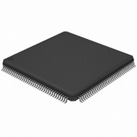
AT32UC3A364-ALUT Atmel, AT32UC3A364-ALUT Datasheet - Page 317

AT32UC3A364-ALUT
Manufacturer Part Number
AT32UC3A364-ALUT
Description
IC MCU 64KB FLASH 144LQFP
Manufacturer
Atmel
Series
AVR®32 UC3r
Specifications of AT32UC3A364-ALUT
Core Processor
AVR
Core Size
32-Bit
Speed
66MHz
Connectivity
EBI/EMI, I²C, IrDA, MMC, SPI, SSC, UART/USART, USB OTG
Peripherals
Brown-out Detect/Reset, DMA, POR, WDT
Number Of I /o
110
Program Memory Size
64KB (64K x 8)
Program Memory Type
FLASH
Ram Size
128K x 8
Voltage - Supply (vcc/vdd)
1.65 V ~ 1.95 V
Data Converters
A/D 8x10b
Oscillator Type
Internal
Operating Temperature
-40°C ~ 85°C
Package / Case
144-LQFP
Processor Series
AT32UC3x
Core
AVR32
Data Bus Width
32 bit
Data Ram Size
96 KB
Interface Type
IrDA/SCI/SCIF/UDI
Maximum Clock Frequency
66 MHz
Number Of Timers
3
Operating Supply Voltage
3 V to 3.6 V
Maximum Operating Temperature
+ 85 C
Mounting Style
SMD/SMT
3rd Party Development Tools
EWAVR32, EWAVR32-BL, KSK-EVK1100-PL
Development Tools By Supplier
ATAVRDRAGON, ATSTK500, ATSTK600, ATAVRISP2, ATAVRONEKIT, ATEXTWIFI, ATEVK1104
Minimum Operating Temperature
- 40 C
Controller Family/series
AT32UC3A
No. Of I/o's
110
Ram Memory Size
64KB
Cpu Speed
66MHz
No. Of Timers
2
Rohs Compliant
Yes
For Use With
ATEVK1104 - KIT DEV/EVAL FOR AVR32 AT32UC3AATAVRONEKIT - KIT AVR/AVR32 DEBUGGER/PROGRMMRATEVK1100 - KIT DEV/EVAL FOR AVR32 AT32UC3A
Lead Free Status / RoHS Status
Lead free / RoHS Compliant
Eeprom Size
-
Lead Free Status / Rohs Status
Lead free / RoHS Compliant
Available stocks
Company
Part Number
Manufacturer
Quantity
Price
- Current page: 317 of 1014
- Download datasheet (16Mb)
32072C–AVR32–2010/03
DMA transfer: Software controls the number of blocks in a DMACA transfer. Once the DMA
transfer has completed, then hardware within the DMACA disables the channel and can gener-
ate an interrupt to signal the completion of the DMA transfer. You can then re-program the
channel for a new DMA transfer.
Single-block DMA transfer: Consists of a single block.
Multi-block DMA transfer: A DMA transfer may consist of multiple DMACA blocks. Multi-block
DMA transfers are supported through block chaining (linked list pointers), auto-reloading of
channel registers, and contiguous blocks. The source and destination can independently select
which method to use.
Scatter: Relevant to destination transfers within a block. The destination System Bus address is
incremented or decremented by a programmed amount -the scatter increment- when a scatter
boundary is reached. The destination System Bus address is incremented or decremented by
the value stored in the destination scatter increment (DSRx.DSI) field, multiplied by the number
of bytes in a single HSB transfer to the destination (decoded value of CTLx.DST_TR_WIDTH)/8.
The number of destination transfers between successive scatter boundaries is programmed into
the Destination Scatter Count (DSC) field of the DSRx register.
Scatter is enabled by writing a ‘1’ to the CTLx.DST_SCATTER_EN bit. The CTLx.DINC field
determines if the address is incremented, decremented or remains fixed when a scatter bound-
ary is reached. If the CTLx.DINC field indicates a fixed-address control throughout a DMA
transfer, then the CTLx.DST_SCATTER_EN bit is ignored, and the scatter feature is automati-
cally disabled.
Gather: Relevant to source transfers within a block. The source System Bus address is incre-
mented or decremented by a programmed amount when a gather boundary is reached. The
number of System Bus transfers between successive gather boundaries is programmed into the
Source Gather Count (SGRx.SGC) field. The source address is incremented or decremented by
the value stored in the source gather increment (SGRx.SGI) field multiplied by the number of
bytes in a single HSB transfer from the source -(decoded value of CTLx.SRC_TR_WIDTH)/8 -
when a gather boundary is reached.
– Single transaction: The length of a single transaction is always 1 and is converted
– Burst transaction: The length of a burst transaction is programmed into the
– Linked lists (block chaining) – A linked list pointer (LLP) points to the location in
– Auto-reloading – The DMACA automatically reloads the channel registers at the
– Contiguous blocks – Where the address between successive blocks is selected to
to a single System Bus transfer.
DMACA. The burst transaction is converted into a sequence of System Bus bursts
and single transfers. DMACA executes each burst transfer by performing
incremental bursts that are no longer than the maximum System Bus burst size set.
The burst transaction length is under program control and normally bears some
relationship to the FIFO sizes in the DMACA and in the source and destination
peripherals.
system memory where the next linked list item (LLI) exists. The LLI is a set of
registers that describe the next block (block descriptor) and an LLP register. The
DMACA fetches the LLI at the beginning of every block when block chaining is
enabled.
end of each block to the value when the channel was first enabled.
be a continuation from the end of the previous block.
AT32UC3A3/A4
317
Related parts for AT32UC3A364-ALUT
Image
Part Number
Description
Manufacturer
Datasheet
Request
R

Part Number:
Description:
KIT DEV/EVAL FOR AT32UC3A3
Manufacturer:
Atmel
Datasheet:

Part Number:
Description:
DEV KIT FOR AVR/AVR32
Manufacturer:
Atmel
Datasheet:

Part Number:
Description:
INTERVAL AND WIPE/WASH WIPER CONTROL IC WITH DELAY
Manufacturer:
ATMEL Corporation
Datasheet:

Part Number:
Description:
Low-Voltage Voice-Switched IC for Hands-Free Operation
Manufacturer:
ATMEL Corporation
Datasheet:

Part Number:
Description:
MONOLITHIC INTEGRATED FEATUREPHONE CIRCUIT
Manufacturer:
ATMEL Corporation
Datasheet:

Part Number:
Description:
AM-FM Receiver IC U4255BM-M
Manufacturer:
ATMEL Corporation
Datasheet:

Part Number:
Description:
Monolithic Integrated Feature Phone Circuit
Manufacturer:
ATMEL Corporation
Datasheet:

Part Number:
Description:
Multistandard Video-IF and Quasi Parallel Sound Processing
Manufacturer:
ATMEL Corporation
Datasheet:

Part Number:
Description:
High-performance EE PLD
Manufacturer:
ATMEL Corporation
Datasheet:

Part Number:
Description:
8-bit Flash Microcontroller
Manufacturer:
ATMEL Corporation
Datasheet:

Part Number:
Description:
2-Wire Serial EEPROM
Manufacturer:
ATMEL Corporation
Datasheet:


