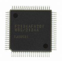
DF2134AFA20V Renesas Electronics America, DF2134AFA20V Datasheet - Page 27

DF2134AFA20V
Manufacturer Part Number
DF2134AFA20V
Description
IC H8S/2100 MCU FLASH 80QFP
Manufacturer
Renesas Electronics America
Series
H8® H8S/2100r
Datasheets
1.HEWH8E10A.pdf
(19 pages)
2.D12312SVTE25V.pdf
(341 pages)
3.DF2134AFA20V.pdf
(1063 pages)
Specifications of DF2134AFA20V
Core Processor
H8S/2000
Core Size
16-Bit
Speed
20MHz
Connectivity
IrDA, SCI
Peripherals
POR, PWM, WDT
Number Of I /o
58
Program Memory Size
128KB (128K x 8)
Program Memory Type
FLASH
Ram Size
4K x 8
Voltage - Supply (vcc/vdd)
4 V ~ 5.5 V
Data Converters
A/D 8x10b; D/A 2x8b
Oscillator Type
Internal
Operating Temperature
-20°C ~ 75°C
Package / Case
80-QFP
For Use With
3DK2166 - DEV EVAL KIT H8S/2166
Lead Free Status / RoHS Status
Lead free / RoHS Compliant
Eeprom Size
-
Available stocks
Company
Part Number
Manufacturer
Quantity
Price
Company:
Part Number:
DF2134AFA20V
Manufacturer:
Renesas Electronics America
Quantity:
10 000
- Current page: 27 of 1063
- Download datasheet (6Mb)
Section 13 Timer Connection [H8S/2138 Group]
13.1 Overview........................................................................................................................... 341
13.2 Register Descriptions ........................................................................................................ 344
13.3 Operation .......................................................................................................................... 355
Section 14 Watchdog Timer (WDT)
14.1 Overview........................................................................................................................... 371
14.2 Register Descriptions ........................................................................................................ 375
14.3 Operation .......................................................................................................................... 381
12.6.4 Contention between Compare-Matches A and B................................................. 338
12.6.5 Switching of Internal Clocks and TCNT Operation............................................. 338
13.1.1 Features................................................................................................................ 341
13.1.2 Block Diagram ..................................................................................................... 342
13.1.3 Input and Output Pins .......................................................................................... 343
13.1.4 Register Configuration......................................................................................... 344
13.2.1 Timer Connection Register I (TCONRI) ............................................................. 344
13.2.2 Timer Connection Register O (TCONRO) .......................................................... 347
13.2.3 Timer Connection Register S (TCONRS)............................................................ 349
13.2.4 Edge Sense Register (SEDGR) ............................................................................ 351
13.2.5 Module Stop Control Register (MSTPCR) .......................................................... 354
13.3.1 PWM Decoding (PDC Signal Generation) .......................................................... 355
13.3.2 Clamp Waveform Generation (CL1/CL2/CL3 Signal Generation) ..................... 357
13.3.3 Measurement of 8-Bit Timer Divided Waveform Period .................................... 358
13.3.4 IHI Signal and 2fH Modification ......................................................................... 360
13.3.5 IVI Signal Fall Modification and IHI Synchronization ....................................... 362
13.3.6 Internal Synchronization Signal Generation
13.3.7 HSYNCO Output ................................................................................................. 367
13.3.8 VSYNCO Output ................................................................................................. 368
13.3.9 CBLANK Output ................................................................................................. 369
14.1.1 Features................................................................................................................ 371
14.1.2 Block Diagram ..................................................................................................... 372
14.1.3 Pin Configuration................................................................................................. 374
14.1.4 Register Configuration......................................................................................... 374
14.2.1 Timer Counter (TCNT)........................................................................................ 375
14.2.2 Timer Control/Status Register (TCSR) ................................................................ 376
14.2.3 System Control Register (SYSCR) ...................................................................... 379
14.2.4 Notes on Register Access..................................................................................... 380
14.3.1 Watchdog Timer Operation ................................................................................. 381
14.3.2 Interval Timer Operation ..................................................................................... 382
(IHG/IVG/CL4 Signal Generation) ..................................................................... 364
.............................................................................. 371
Rev. 4.00 Jun 06, 2006 page xxv of liv
...................................................... 341
Related parts for DF2134AFA20V
Image
Part Number
Description
Manufacturer
Datasheet
Request
R

Part Number:
Description:
KIT STARTER FOR M16C/29
Manufacturer:
Renesas Electronics America
Datasheet:

Part Number:
Description:
KIT STARTER FOR R8C/2D
Manufacturer:
Renesas Electronics America
Datasheet:

Part Number:
Description:
R0K33062P STARTER KIT
Manufacturer:
Renesas Electronics America
Datasheet:

Part Number:
Description:
KIT STARTER FOR R8C/23 E8A
Manufacturer:
Renesas Electronics America
Datasheet:

Part Number:
Description:
KIT STARTER FOR R8C/25
Manufacturer:
Renesas Electronics America
Datasheet:

Part Number:
Description:
KIT STARTER H8S2456 SHARPE DSPLY
Manufacturer:
Renesas Electronics America
Datasheet:

Part Number:
Description:
KIT STARTER FOR R8C38C
Manufacturer:
Renesas Electronics America
Datasheet:

Part Number:
Description:
KIT STARTER FOR R8C35C
Manufacturer:
Renesas Electronics America
Datasheet:

Part Number:
Description:
KIT STARTER FOR R8CL3AC+LCD APPS
Manufacturer:
Renesas Electronics America
Datasheet:

Part Number:
Description:
KIT STARTER FOR RX610
Manufacturer:
Renesas Electronics America
Datasheet:

Part Number:
Description:
KIT STARTER FOR R32C/118
Manufacturer:
Renesas Electronics America
Datasheet:

Part Number:
Description:
KIT DEV RSK-R8C/26-29
Manufacturer:
Renesas Electronics America
Datasheet:

Part Number:
Description:
KIT STARTER FOR SH7124
Manufacturer:
Renesas Electronics America
Datasheet:

Part Number:
Description:
KIT STARTER FOR H8SX/1622
Manufacturer:
Renesas Electronics America
Datasheet:

Part Number:
Description:
KIT DEV FOR SH7203
Manufacturer:
Renesas Electronics America
Datasheet:


