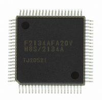
DF2134AFA20V Renesas Electronics America, DF2134AFA20V Datasheet - Page 120

DF2134AFA20V
Manufacturer Part Number
DF2134AFA20V
Description
IC H8S/2100 MCU FLASH 80QFP
Manufacturer
Renesas Electronics America
Series
H8® H8S/2100r
Datasheets
1.HEWH8E10A.pdf
(19 pages)
2.D12312SVTE25V.pdf
(341 pages)
3.DF2134AFA20V.pdf
(1063 pages)
Specifications of DF2134AFA20V
Core Processor
H8S/2000
Core Size
16-Bit
Speed
20MHz
Connectivity
IrDA, SCI
Peripherals
POR, PWM, WDT
Number Of I /o
58
Program Memory Size
128KB (128K x 8)
Program Memory Type
FLASH
Ram Size
4K x 8
Voltage - Supply (vcc/vdd)
4 V ~ 5.5 V
Data Converters
A/D 8x10b; D/A 2x8b
Oscillator Type
Internal
Operating Temperature
-20°C ~ 75°C
Package / Case
80-QFP
For Use With
3DK2166 - DEV EVAL KIT H8S/2166
Lead Free Status / RoHS Status
Lead free / RoHS Compliant
Eeprom Size
-
Available stocks
Company
Part Number
Manufacturer
Quantity
Price
Company:
Part Number:
DF2134AFA20V
Manufacturer:
Renesas Electronics America
Quantity:
10 000
- Current page: 120 of 1063
- Download datasheet (6Mb)
Section 2 CPU
2.8.3
The exception-handling state is a transient state that occurs when the CPU alters the normal
processing flow due to a reset, interrupt, or trap instruction. The CPU fetches a start address
(vector) from the exception vector table and branches to that address.
Types of Exception Handling and Their Priority: Exception handling is performed for resets,
interrupts, and trap instructions. Table 2.7 indicates the types of exception handling and their
priority. Trap instruction exception handling is always accepted in the program execution state.
Exception handling and the stack structure depend on the interrupt control mode set in SYSCR.
Table 2.7
Priority
High
Low
Notes: 1. Interrupts are not detected at the end of the ANDC, ORC, XORC, and LDC instructions,
Reset Exception Handling: After the RES pin has gone low and the reset state has been entered,
when RES goes high again, reset exception handling starts. When reset exception handling starts
the CPU fetches a start address (vector) from the exception vector table and starts program
execution from that address. All interrupts, including NMI, are disabled during reset exception
handling and after it ends.
Interrupt Exception Handling and Trap Instruction Exception Handling: When interrupt or
trap-instruction exception handling begins, the CPU references the stack pointer (ER7) and pushes
the program counter and other control registers onto the stack. Next, the CPU alters the settings of
the interrupt mask bits in the control registers. Then the CPU fetches a start address (vector) from
the exception vector table and program execution starts from that start address.
Rev. 4.00 Jun 06, 2006 page 64 of 1004
REJ09B0301-0400
2. Trap instruction exception handling is always accepted in the program execution state.
Exception-Handling State
or immediately after reset exception handling.
Type of Exception
Reset
Interrupt
Trap instruction
Exception Handling Types and Priority
Detection Timing
Synchronized with clock
End of instruction
execution or end of
exception-handling
sequence *
When TRAPA instruction
is executed
1
Start of Exception Handling
Exception handling starts
immediately after a low-to-high
transition at the RES pin, or
when the watchdog timer
overflows.
When an interrupt is requested,
exception handling starts at the
end of the current instruction or
current exception-handling
sequence.
Exception handling starts when
a trap (TRAPA) instruction is
executed. *
2
Related parts for DF2134AFA20V
Image
Part Number
Description
Manufacturer
Datasheet
Request
R

Part Number:
Description:
KIT STARTER FOR M16C/29
Manufacturer:
Renesas Electronics America
Datasheet:

Part Number:
Description:
KIT STARTER FOR R8C/2D
Manufacturer:
Renesas Electronics America
Datasheet:

Part Number:
Description:
R0K33062P STARTER KIT
Manufacturer:
Renesas Electronics America
Datasheet:

Part Number:
Description:
KIT STARTER FOR R8C/23 E8A
Manufacturer:
Renesas Electronics America
Datasheet:

Part Number:
Description:
KIT STARTER FOR R8C/25
Manufacturer:
Renesas Electronics America
Datasheet:

Part Number:
Description:
KIT STARTER H8S2456 SHARPE DSPLY
Manufacturer:
Renesas Electronics America
Datasheet:

Part Number:
Description:
KIT STARTER FOR R8C38C
Manufacturer:
Renesas Electronics America
Datasheet:

Part Number:
Description:
KIT STARTER FOR R8C35C
Manufacturer:
Renesas Electronics America
Datasheet:

Part Number:
Description:
KIT STARTER FOR R8CL3AC+LCD APPS
Manufacturer:
Renesas Electronics America
Datasheet:

Part Number:
Description:
KIT STARTER FOR RX610
Manufacturer:
Renesas Electronics America
Datasheet:

Part Number:
Description:
KIT STARTER FOR R32C/118
Manufacturer:
Renesas Electronics America
Datasheet:

Part Number:
Description:
KIT DEV RSK-R8C/26-29
Manufacturer:
Renesas Electronics America
Datasheet:

Part Number:
Description:
KIT STARTER FOR SH7124
Manufacturer:
Renesas Electronics America
Datasheet:

Part Number:
Description:
KIT STARTER FOR H8SX/1622
Manufacturer:
Renesas Electronics America
Datasheet:

Part Number:
Description:
KIT DEV FOR SH7203
Manufacturer:
Renesas Electronics America
Datasheet:


