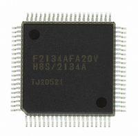
DF2134AFA20V Renesas Electronics America, DF2134AFA20V Datasheet - Page 24

DF2134AFA20V
Manufacturer Part Number
DF2134AFA20V
Description
IC H8S/2100 MCU FLASH 80QFP
Manufacturer
Renesas Electronics America
Series
H8® H8S/2100r
Datasheets
1.HEWH8E10A.pdf
(19 pages)
2.D12312SVTE25V.pdf
(341 pages)
3.DF2134AFA20V.pdf
(1063 pages)
Specifications of DF2134AFA20V
Core Processor
H8S/2000
Core Size
16-Bit
Speed
20MHz
Connectivity
IrDA, SCI
Peripherals
POR, PWM, WDT
Number Of I /o
58
Program Memory Size
128KB (128K x 8)
Program Memory Type
FLASH
Ram Size
4K x 8
Voltage - Supply (vcc/vdd)
4 V ~ 5.5 V
Data Converters
A/D 8x10b; D/A 2x8b
Oscillator Type
Internal
Operating Temperature
-20°C ~ 75°C
Package / Case
80-QFP
For Use With
3DK2166 - DEV EVAL KIT H8S/2166
Lead Free Status / RoHS Status
Lead free / RoHS Compliant
Eeprom Size
-
Available stocks
Company
Part Number
Manufacturer
Quantity
Price
Company:
Part Number:
DF2134AFA20V
Manufacturer:
Renesas Electronics America
Quantity:
10 000
- Current page: 24 of 1063
- Download datasheet (6Mb)
8.6
8.7
8.8
8.9
8.10 Port 9................................................................................................................................. 234
Section 9 8-Bit PWM Timers [H8S/2138 Group]
9.1
9.2
9.3
Rev. 4.00 Jun 06, 2006 page xxii of liv
Port 5................................................................................................................................. 218
8.6.1
8.6.2
8.6.3
Port 6................................................................................................................................. 221
8.7.1
8.7.2
8.7.3
8.7.4
Port 7................................................................................................................................. 228
8.8.1
8.8.2
8.8.3
Port 8................................................................................................................................. 230
8.9.1
8.9.2
8.9.3
8.10.1 Overview.............................................................................................................. 234
8.10.2 Register Configuration......................................................................................... 235
8.10.3 Pin Functions ....................................................................................................... 236
Overview........................................................................................................................... 241
9.1.1
9.1.2
9.1.3
9.1.4
Register Descriptions ........................................................................................................ 244
9.2.1
9.2.2
9.2.3
9.2.4
9.2.5
9.2.6
9.2.7
9.2.8
9.2.9
9.2.10 Module Stop Control Register (MSTPCR) .......................................................... 250
Operation .......................................................................................................................... 251
Overview.............................................................................................................. 218
Register Configuration......................................................................................... 218
Pin Functions ....................................................................................................... 220
Overview.............................................................................................................. 221
Register Configuration......................................................................................... 222
Pin Functions ....................................................................................................... 225
MOS Input Pull-Up Function............................................................................... 227
Overview.............................................................................................................. 228
Register Configuration......................................................................................... 228
Pin Functions ....................................................................................................... 229
Overview.............................................................................................................. 230
Register Configuration......................................................................................... 230
Pin Functions ....................................................................................................... 231
Features................................................................................................................ 241
Block Diagram ..................................................................................................... 242
Pin Configuration................................................................................................. 243
Register Configuration......................................................................................... 243
PWM Register Select (PWSL)............................................................................. 244
PWM Data Registers (PWDR0 to PWDR15) ...................................................... 246
PWM Data Polarity Registers A and B (PWDPRA and PWDPRB).................... 246
PWM Output Enable Registers A and B (PWOERA and PWOERB) ................. 247
Peripheral Clock Select Register (PCSR) ............................................................ 248
Port 1 Data Direction Register (P1DDR)............................................................. 248
Port 2 Data Direction Register (P2DDR)............................................................. 249
Port 1 Data Register (P1DR)................................................................................ 249
Port 2 Data Register (P2DR)................................................................................ 249
...................................................... 241
Related parts for DF2134AFA20V
Image
Part Number
Description
Manufacturer
Datasheet
Request
R

Part Number:
Description:
KIT STARTER FOR M16C/29
Manufacturer:
Renesas Electronics America
Datasheet:

Part Number:
Description:
KIT STARTER FOR R8C/2D
Manufacturer:
Renesas Electronics America
Datasheet:

Part Number:
Description:
R0K33062P STARTER KIT
Manufacturer:
Renesas Electronics America
Datasheet:

Part Number:
Description:
KIT STARTER FOR R8C/23 E8A
Manufacturer:
Renesas Electronics America
Datasheet:

Part Number:
Description:
KIT STARTER FOR R8C/25
Manufacturer:
Renesas Electronics America
Datasheet:

Part Number:
Description:
KIT STARTER H8S2456 SHARPE DSPLY
Manufacturer:
Renesas Electronics America
Datasheet:

Part Number:
Description:
KIT STARTER FOR R8C38C
Manufacturer:
Renesas Electronics America
Datasheet:

Part Number:
Description:
KIT STARTER FOR R8C35C
Manufacturer:
Renesas Electronics America
Datasheet:

Part Number:
Description:
KIT STARTER FOR R8CL3AC+LCD APPS
Manufacturer:
Renesas Electronics America
Datasheet:

Part Number:
Description:
KIT STARTER FOR RX610
Manufacturer:
Renesas Electronics America
Datasheet:

Part Number:
Description:
KIT STARTER FOR R32C/118
Manufacturer:
Renesas Electronics America
Datasheet:

Part Number:
Description:
KIT DEV RSK-R8C/26-29
Manufacturer:
Renesas Electronics America
Datasheet:

Part Number:
Description:
KIT STARTER FOR SH7124
Manufacturer:
Renesas Electronics America
Datasheet:

Part Number:
Description:
KIT STARTER FOR H8SX/1622
Manufacturer:
Renesas Electronics America
Datasheet:

Part Number:
Description:
KIT DEV FOR SH7203
Manufacturer:
Renesas Electronics America
Datasheet:


