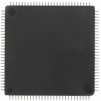
DF70845AD80FPV Renesas Electronics America, DF70845AD80FPV Datasheet - Page 41

DF70845AD80FPV
Manufacturer Part Number
DF70845AD80FPV
Description
IC SUPERH MCU FLASH 112LQFP
Manufacturer
Renesas Electronics America
Series
SuperH® SH7080r
Datasheet
1.DF70844AD80FPV.pdf
(1644 pages)
Specifications of DF70845AD80FPV
Core Size
32-Bit
Program Memory Size
512KB (512K x 8)
Core Processor
SH-2
Speed
80MHz
Connectivity
EBI/EMI, FIFO, I²C, SCI, SSU
Peripherals
DMA, POR, PWM, WDT
Number Of I /o
76
Program Memory Type
FLASH
Ram Size
32K x 8
Voltage - Supply (vcc/vdd)
3 V ~ 5.5 V
Data Converters
A/D 8x10b
Oscillator Type
Internal
Operating Temperature
-40°C ~ 85°C
Package / Case
112-LQFP
No. Of I/o's
76
Ram Memory Size
32KB
Cpu Speed
80MHz
Digital Ic Case Style
LQFP
Supply Voltage Range
3V To 3.6V, 4.5V To 5.5V
Embedded Interface Type
I2C, SCI
Rohs Compliant
Yes
Lead Free Status / RoHS Status
Lead free / RoHS Compliant
For Use With
R0K570865S001BE - KIT STARTER FOR SH7086R0K570865S000BE - KIT STARTER FOR SH7086HS0005KCU11H - EMULATOR E10A-USB H8S(X),SH2(A)
Eeprom Size
-
Lead Free Status / RoHS Status
Lead free / RoHS Compliant, Lead free / RoHS Compliant
Available stocks
Company
Part Number
Manufacturer
Quantity
Price
Company:
Part Number:
DF70845AD80FPV
Manufacturer:
TAIYO
Quantity:
40 000
Company:
Part Number:
DF70845AD80FPV
Manufacturer:
Renesas Electronics America
Quantity:
10 000
- Current page: 41 of 1644
- Download datasheet (10Mb)
Figure 19.6 Definitions of A/D Conversion Accuracy ............................................................... 971
Figure 19.7 Example of Analog Input Circuit ............................................................................ 973
Figure 19.8 Example of Analog Input Protection Circuit ........................................................... 974
Section 20 Compare Match Timer (CMT)
Figure 20.1 Block Diagram of CMT .......................................................................................... 975
Figure 20.2 Counter Operation ................................................................................................... 980
Figure 20.3 Count Timing .......................................................................................................... 980
Figure 20.4 Timing of CMF Setting ........................................................................................... 981
Figure 20.5 Conflict between Write and Compare-Match Processes of CMCNT ...................... 982
Figure 20.6 Conflict between Word-Write and Count-Up Processes of CMCNT...................... 983
Figure 20.7 Conflict between Byte-Write and Count-Up Processes of CMCNT ....................... 984
Section 22 I/O Ports
Figure 22.1 Port A (SH7083).................................................................................................... 1162
Figure 22.2 Port A (SH7084).................................................................................................... 1163
Figure 22.3 Port A (SH7085).................................................................................................... 1164
Figure 22.4 Port A (SH7086).................................................................................................... 1165
Figure 22.5 Port B (SH7083).................................................................................................... 1177
Figure 22.6 Port B (SH7084, SH7085, SH7086)...................................................................... 1177
Figure 22.7 Port C (SH7083, SH7084, SH7085)...................................................................... 1183
Figure 22.8 Port C (SH7086).................................................................................................... 1184
Figure 22.9 Port D (SH7083, SH7084)..................................................................................... 1191
Figure 22.10 Port D (SH7085, SH7086)................................................................................... 1192
Figure 22.11 Port E (SH7083) .................................................................................................. 1199
Figure 22.12 Port E (SH7084) .................................................................................................. 1200
Figure 22.13 Port E (SH7085) .................................................................................................. 1201
Figure 22.14 Port E (SH7086) .................................................................................................. 1202
Figure 22.15 Port F (SH7083, SH7084, SH7085) .................................................................... 1211
Figure 22.16 Port F (SH7086) .................................................................................................. 1211
Section 23 Flash Memory
Figure 23.1 Block Diagram of Flash Memory.......................................................................... 1217
Figure 23.2 Mode Transition of Flash Memory........................................................................ 1218
Figure 23.3 Flash Memory Configuration ................................................................................ 1221
Figure 23.4 Block Division of User MAT ................................................................................ 1222
Figure 23.5 Overview of User Procedure Program................................................................... 1223
Figure 23.6 System Configuration in Boot Mode..................................................................... 1252
Figure 23.7 Automatic Adjustment Operation of SCI Bit Rate ................................................ 1253
Figure 23.8 State Transitions in Boot Mode ............................................................................. 1255
Figure 23.9 Programming/Erasing Overview Flow.................................................................. 1256
Figure 23.10 RAM Map after Download.................................................................................. 1257
Rev. 3.00 May 17, 2007 Page xli of Iviii
Related parts for DF70845AD80FPV
Image
Part Number
Description
Manufacturer
Datasheet
Request
R

Part Number:
Description:
KIT STARTER FOR M16C/29
Manufacturer:
Renesas Electronics America
Datasheet:

Part Number:
Description:
KIT STARTER FOR R8C/2D
Manufacturer:
Renesas Electronics America
Datasheet:

Part Number:
Description:
R0K33062P STARTER KIT
Manufacturer:
Renesas Electronics America
Datasheet:

Part Number:
Description:
KIT STARTER FOR R8C/23 E8A
Manufacturer:
Renesas Electronics America
Datasheet:

Part Number:
Description:
KIT STARTER FOR R8C/25
Manufacturer:
Renesas Electronics America
Datasheet:

Part Number:
Description:
KIT STARTER H8S2456 SHARPE DSPLY
Manufacturer:
Renesas Electronics America
Datasheet:

Part Number:
Description:
KIT STARTER FOR R8C38C
Manufacturer:
Renesas Electronics America
Datasheet:

Part Number:
Description:
KIT STARTER FOR R8C35C
Manufacturer:
Renesas Electronics America
Datasheet:

Part Number:
Description:
KIT STARTER FOR R8CL3AC+LCD APPS
Manufacturer:
Renesas Electronics America
Datasheet:

Part Number:
Description:
KIT STARTER FOR RX610
Manufacturer:
Renesas Electronics America
Datasheet:

Part Number:
Description:
KIT STARTER FOR R32C/118
Manufacturer:
Renesas Electronics America
Datasheet:

Part Number:
Description:
KIT DEV RSK-R8C/26-29
Manufacturer:
Renesas Electronics America
Datasheet:

Part Number:
Description:
KIT STARTER FOR SH7124
Manufacturer:
Renesas Electronics America
Datasheet:

Part Number:
Description:
KIT STARTER FOR H8SX/1622
Manufacturer:
Renesas Electronics America
Datasheet:

Part Number:
Description:
KIT DEV FOR SH7203
Manufacturer:
Renesas Electronics America
Datasheet:


