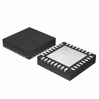
EFM32G200F64 Energy Micro, EFM32G200F64 Datasheet - Page 57

EFM32G200F64
Manufacturer Part Number
EFM32G200F64
Description
MCU 32BIT 64KB FLASH 32-QFN
Manufacturer
Energy Micro
Series
Geckor
Datasheets
1.EFM32G200F16.pdf
(63 pages)
2.EFM32G200F16.pdf
(10 pages)
3.EFM32G200F16.pdf
(463 pages)
4.EFM32G200F16.pdf
(136 pages)
Specifications of EFM32G200F64
Core Processor
ARM® Cortex-M3™
Core Size
32-Bit
Speed
32MHz
Connectivity
EBI/EMI, I²C, IrDA, SmartCard, SPI, UART/USART
Peripherals
Brown-out Detect/Reset, DMA, POR, PWM, WDT
Number Of I /o
24
Program Memory Size
64KB (64K x 8)
Program Memory Type
FLASH
Ram Size
16K x 8
Voltage - Supply (vcc/vdd)
1.8 V ~ 3.8 V
Data Converters
A/D 4x12b, D/A 1x12b
Oscillator Type
External
Operating Temperature
-40°C ~ 85°C
Package / Case
32-VQFN Exposed Pad
Processor Series
EFM32G200
Core
ARM Cortex-M3
Data Bus Width
32 bit
Data Ram Size
16 KB
Interface Type
I2C, UART
Maximum Clock Frequency
32 MHz
Number Of Programmable I/os
24
Number Of Timers
2
Operating Supply Voltage
1.8 V to 3.8 V
Maximum Operating Temperature
+ 85 C
Mounting Style
SMD/SMT
Minimum Operating Temperature
- 40 C
Lead Free Status / RoHS Status
Lead free / RoHS Compliant
Eeprom Size
-
Lead Free Status / Rohs Status
Details
Available stocks
Company
Part Number
Manufacturer
Quantity
Price
- EFM32G200F16 PDF datasheet
- EFM32G200F16 PDF datasheet #2
- EFM32G200F16 PDF datasheet #3
- EFM32G200F16 PDF datasheet #4
- Current page: 57 of 463
- Download datasheet (8Mb)
8.4.4 Interaction with the EMU
8.4.5 Interrupts
8.5 Examples
2010-09-06 - d0001_Rev1.00
Table 8.11. DMA cycle of 12 bytes using a halfword increment
1
2
The DMA interacts with the Energy Management Unit (EMU) to allow transfers from e.g. the LEUART
to occur in EM2. The EMU can wake up the DMA sufficiently long to allow data transfers to occur. See
section "DMA Support" in the LEUART documentation.
The PL230 dma_done[n:0] signals, one for each channel, as well as the dma_err signal, are available as
interrupts to the Cortex-M3 core. They are combined into one interrupt vector, DMA_INT. If interrupts for
the DMA is enabled in the ARM Cortex-M3 core, an interrupt will be made if one or more of the interrupt
flags in DMA_IF and their corresponding bits in DMA_IEN are set.
A basic example of how to program the DMA for transferring 42 bytes from the USART1 to
memory location 0x20003420. Assumes that the channel 0 is currently disabled, and that the
DMA_ALTCTRLBASE register has already been configured.
This value is the result of count being shifted left by the value of dst_inc.
After the controller completes the DMA cycle it invalidates the channel_cfg memory location by clearing the cycle_ctrl field.
Initial values of channel_cfg, prior to the DMA cycle
src_size = b00, dst_inc = b01, n_minus_1 = b1011, cycle_ctrl = 1, R_power = b11
DMA transfers
Values of channel_cfg after 2
src_size = b00, dst_inc = b01, n_minus_1 = b011, cycle_ctrl = 1, R_power = b11
DMA transfers
Final values of channel_cfg, after the DMA cycle
src_size = b00, dst_inc = b01, n_minus_1 = 0, cycle_ctrl = 0
End Pointer
0x5E7
0x5E7
0x5E7
0x5E7
0x5E7
0x5E7
0x5E7
0x5E7
End Pointer
0x5E7
0x5E7
0x5E7
0x5E7
R
DMA transfers
Count
11
10
9
8
7
6
5
4
Count
3
2
1
0
Difference
0x16
0x14
0x12
0x10
0xE
0xC
0xA
0x8
Difference
0x6
0x4
0x2
0x0
2
, R_power = b11
...the world's most energy friendly microcontrollers
57
1
Address
0x5D1
0x5D3
0x5D5
0x5D7
0x5D9
0x5DB
0x5DD
0x5DF
Address
0x5E1
0x5E3
0x5E5
0x5E7
www.energymicro.com
Related parts for EFM32G200F64
Image
Part Number
Description
Manufacturer
Datasheet
Request
R

Part Number:
Description:
KIT STARTER EFM32 GECKO
Manufacturer:
Energy Micro
Datasheet:

Part Number:
Description:
KIT DEV EFM32 GECKO LCD SUPPORT
Manufacturer:
Energy Micro
Datasheet:

Part Number:
Description:
BOARD PROTOTYPING FOR EFM32
Manufacturer:
Energy Micro
Datasheet:

Part Number:
Description:
KIT DEVELOPMENT EFM32 GECKO
Manufacturer:
Energy Micro
Datasheet:

Part Number:
Description:
MCU, MPU & DSP Development Tools TG840 Sample Kit
Manufacturer:
Energy Micro
Datasheet:

Part Number:
Description:
MCU, MPU & DSP Development Tools TG Starter Kit
Manufacturer:
Energy Micro
Datasheet:

Part Number:
Description:
MCU, MPU & DSP Development Tools TG108 Sample Kit
Manufacturer:
Energy Micro

Part Number:
Description:
MCU, MPU & DSP Development Tools TG210 Sample Kit
Manufacturer:
Energy Micro
Datasheet:

Part Number:
Description:
MCU, MPU & DSP Development Tools TG822 Sample Kit
Manufacturer:
Energy Micro
Datasheet:

Part Number:
Description:
MCU, MPU & DSP Development Tools TG230 Sample Kit
Manufacturer:
Energy Micro

Part Number:
Description:
SAMPLE KIT (SMALL BOX - CONTAINING 2 DEVICES)
Manufacturer:
Energy Micro

Part Number:
Description:
SAMPLE KIT (SMALL BOX - CONTAINING 2 DEVICES)
Manufacturer:
Energy Micro


